برق، الکترونیک، الکتروتکنیک، مکاترونیک، پزشکی، کشاورزی

برق، الکترونیک، الکتروتکنیک، مکاترونیک، پزشکی، کشاورزی و

برق، الکترونیک، الکتروتکنیک، مکاترونیک، پزشکی، کشاورزی

برق، الکترونیک، الکتروتکنیک، مکاترونیک، پزشکی، کشاورزی و

داده هایی در مورد برق، الکترونیک، الکتروتکنیک، مکاترونیک، پزشکی، کشاورزی و

تبلیغات
آخرین نظرات

۴۵ مطلب با موضوع «برق الکترونیک رباتیک :: آردوینو و سایربردها» ثبت شده است

دوربین Pixy camera برای چشم نویس

ShahBaz | يكشنبه, ۶ دی ۱۳۹۴، ۰۹:۲۵ ب.ظ

Pixy camera: detect the colour of the objects and track their position

By  on November 20, 2014

Here we present our first tests with the Pixy camera, a device capable of detecting the colour of the objects, and to track their position.

header

Until a short time ago, it was really difficult to develop applications able to take advantage of artificial vision algorithms, and most of all by using systems with limited hardware resources.

Luckily, however, things have changed now: in addition to the various open source frameworks that help developers to easily implement even the most complex algorithms, complete peripherals are spreading, be it for the hardware part (providing the acquisition of images coming from the outside world), or for the software part (able to analyze and read such images). With such peripherals it is possible to create applications provided with artificial vision, in a really simple way.

It is enough to use these devices coupled with a microcontroller or with a prototyping board, such as Arduino, for example. These peripherals deal with the whole part concerning calculations, thus freeing hardware resources of the device they’re connected to, and exchanging only the essential information with it. In this manner anyone will be able to create applications capable of observing and analyzing the surrounding environment, in an extremely simple way.

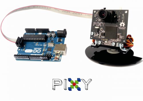
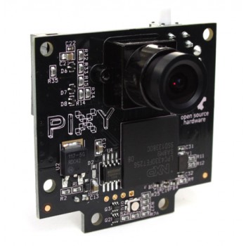
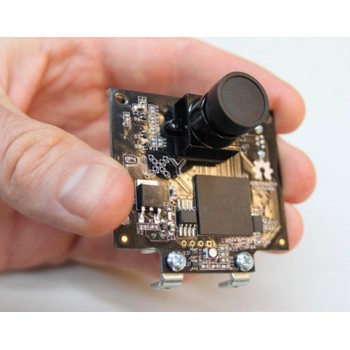
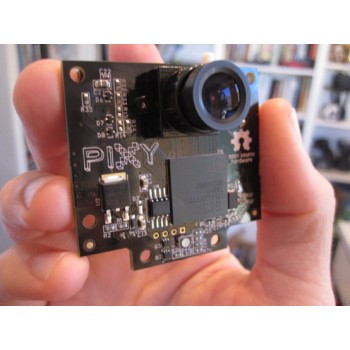
In this article we will deal with the examination of the operation of the Pixy camera, an open source device capable of locating the position of objects, and to communicate the coordinates to Arduino or other microcontrollers.


INSTALLING THE NECESSARY COMPONENTS

In this post we will use the pan/tilt module as well: it is an accessory that allows Pixy cameras to follow the changes in the objects position.

Once all the hardware material has been retrieved, it is possible to download the management software, that is needed to easily set up the objects that the Pixy camera will have to recognize, and to debug the same. The software is named PixyMon and it is possible to retrieve it at the following address: http://cmucam.org/projects/cmucam5/files.

fig1


PIXYMON: THE MANAGEMENT SOFTWARE

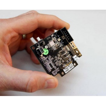
Once the installation procedure of the software is complete, we may connect the Pixy Camera to our PC. On the back side of Pixy a Mini-USB type connector can be found; let’s get the suitable cable then and connect the video camera to our computer.

fig2

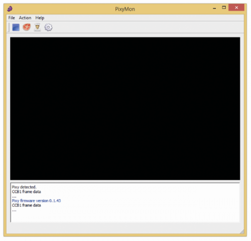
Once the connection procedure is complete, it is possible to open the PixyMon program.

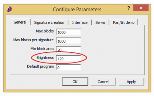
To ensure that the black area is replaced by the images from the video flow, it will be enough to click on the steak-shaped icon, placed up and on the left. If the images turn out to be too dark, it is possible to modify Pixy’s brightness. From the “Configure Parameters” menu (that can be accessed by clicking on the cog-shaped icon), we may modify the Brightness parameter. By increasing this parameter, images will be brighter, vice versa they will be darker. Pixy is capable of increasing or reducing the brightness automatically, however if the object to detect is too dark or too bright, it will be necessary to adjust the brightness value.

fig3

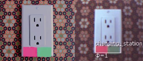
At this stage, we may make Pixy learn the object to detect. The device will recognize the item depending on his colour, thus it is important that it is as much as possible homogeneous. Once this premise has been made, we may start the learning phase. We have to place the object to detect before the camera lens, whereupon, from the Action menu, we have to select “Set Signature 1…”. Once this has been done, we have to highlight the body of the object, by keeping the left mouse button pressed. By releasing the mouse button, the video camera will memorize the item’s colour.

fig5

It is also possible to memorize the item without having to use PixyMon. By pressing the button placed on the superior side of the video camera, and by respecting the appropriate sequence, it is in fact possible to memorize the object placed before the camera lens. This method is however more complex and we will see it when we will connect the video camera to Arduino.

Independently from the mode used, Pixy is capable of memorizing up to seven different objects. The video camera will keep them in memory until they are deleted or overwritten. Thus disconnecting Pixy from the PC or from his power source will not cause the deletion of the learned items. The PixyMon management software allows us to test the pan/tilt system as well; to do so it is needed to memorize at least an object, whereupon it will be enough to click on “Run pan/tilt demo” from the Action menu. We will then see the pan/tilt module’s servos that will move the video camera, so to frame on the memorized object. It is possible that during the demo of the pan/tilt system, the video camera is disconnected from the PC many times. This happens if you possess a low quality USB cable or if the PC we’re using has a sub-optimal USB ports management.


CONNECTING ARDUINO

fig6

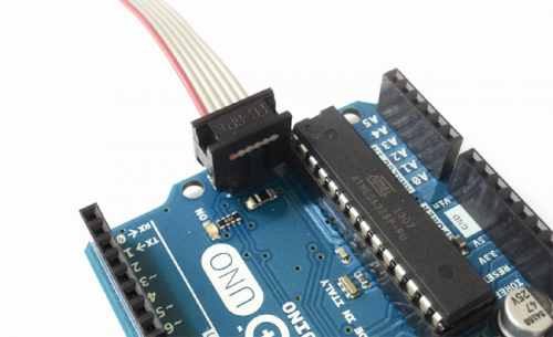
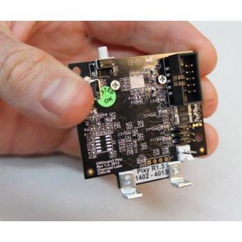
It is quite simple to connect Pixy to Arduino: you just need to pick up the flat cable contained in the video camera package, and to connect the biggest terminal to the back side of Pixy (the connector on the back prevents from getting it in the wrong way), and finally to connect the smaller terminal to Arduino. Make attention to the orientation of the red cable. At this stage we may connect Arduino to our PC and load our first sketches.

It is possible to download the libraries and the sample sketches from the following link:  http://cmucam.org/attachments/download/ 1065/arduino_pixy-0.1.5.zip.

To import the libraries it is needed to open Arduino’s IDE, and then, from the Sketch menu, select the “Import Library…” entry, then “Add Library…” and finally select the folder in which the files you just downloaded from the zip archive are kept.

This operation will load the sample sketches as well. To see their code it is enough to click on the File menu, then on Examples and lastly, on the Pixy submenu.


FIRST SKETCH: HELLO WORLD

1
2
3
4
5
6
7
8
9
10
11
12
13
14
15
16
17
18
19
20
21
22
23
24
25
26
27
28
29
30
31
32
33
34
35
36
37
38
39
40
41
42
43
44
45
46
47
48
49
50
//
// begin license header
//
// This file is part of Pixy CMUcam5 or “Pixy” for short
//
// All Pixy source code is provided under the terms of the
// GNU General Public License v2 (http://www.gnu.org/licenses/gpl-2.0.html).
// Those wishing to use Pixy source code, software and/or
// technologies under different licensing terms should contact us at
// cmucam@cs.cmu.edu. Such licensing terms are available for
// all portions of the Pixy codebase presented here.
//
// end license header
//
/*
06.04.2014 v0.1.3 John Leimon
+ Now using pixy.init() to initialize Pixy in setup().
*/
#include <SPI.h>
#include <Pixy.h>
Pixy pixy;
void setup()
{
Serial.begin(9600);
Serial.print(“Starting...\n”);
pixy.init();
}
void loop()
{
static int i = 0;
int j;
uint16_t blocks;
char buf[32];
blocks = pixy.getBlocks();
if (blocks)
{
i++;
if (i%50==0)
{
sprintf(buf, “Detected %d:\n”, blocks);
Serial.print(buf);
for (j=0; j<blocks; j++)
{
sprintf(buf, “ block %d: “, j);
Serial.print(buf);
pixy.blocks[j].print();
}
}
}
}

Overall, the sample sketches are four. The first sketch is named hello_world, and the source can be seen in Listing 1. As a first thing, the libraries are imported, as required to create the correct communication between Arduino and the video camera. Later, a Pixy-type object is created, and it is initialized by the setup function.

The serial communication with the PC is also set up with this function: in this manner we will be able to see the various debug messages. The getBlocks() method, recalled in the body of the loop function, is needed to count how many memorized objects are before the video camera lens. The method returns an integer, whose value is given by the total number of recognized objects. For each identified object, it is possible to retrieve a series of information pieces, such as his coordinates or his dimensions (in pixels), for example.

The following for cycle is needed for this purpose exactly. Each recognized item is automatically saved in the array blocks of the Pixy object; the pixy.blocks[j].print() instruction then allows us to access the identified object and to print the relative information. In addition to the print method, each object also has the following attributes: x, y, width, height and signature. This last attribute contains the number of the identified object, varying from 1 to 7, depending on the order the item has been memorized.


SECOND SKETCH: PAN/TILT

1
2
3
4
5
6
7
8
9
10
11
12
13
14
15
16
17
18
19
20
21
22
23
24
25
26
27
28
29
30
31
32
33
34
35
36
37
38
39
40
41
42
43
44
45
46
47
48
49
50
51
52
53
54
55
56
57
58
59
60
61
62
63
64
65
66
67
68
69
70
71
72
73
74
75
76
77
78
79
80
81
82
83
84
85
86
87
88
89
90
91
92
93
//
// begin license header
//
// This file is part of Pixy CMUcam5 or “Pixy” for short
//
// All Pixy source code is provided under the terms of the
// GNU General Public License v2 (http://www.gnu.org/licenses/gpl-2.0.html).
// Those wishing to use Pixy source code, software and/or
// technologies under different licensing terms should contact us at
// cmucam@cs.cmu.edu. Such licensing terms are available for
// all portions of the Pixy codebase presented here.
//
// end license header
//
#include <SPI.h>
#include <Pixy.h>
#define X_CENTER 160L
#define Y_CENTER 100L
#define RCS_MIN_POS 0L
#define RCS_MAX_POS 1000L
#define RCS_CENTER_POS ((RCS_MAX_POS-RCS_MIN_POS)/2)
class ServoLoop
{
public:
ServoLoop(int32_t pgain, int32_t dgain);
void update(int32_t error);
int32_t m_pos;
int32_t m_prevError;
int32_t m_pgain;
int32_t m_dgain;
};
ServoLoop panLoop(500, 800);
ServoLoop tiltLoop(700, 900);
ServoLoop::ServoLoop(int32_t pgain, int32_t dgain)
{
m_pos = RCS_CENTER_POS;
m_pgain = pgain;
m_dgain = dgain;
m_prevError = 0x80000000L;
}
void ServoLoop::update(int32_t error)
{
long int vel;
char buf[32];
if (m_prevError!=0x80000000)
{
vel = (error*m_pgain + (error - m_prevError)*m_dgain)>>10;
//sprintf(buf, “%ld\n”, vel);
//Serial.print(buf);
m_pos += vel;
if (m_pos>RCS_MAX_POS)
m_pos = RCS_MAX_POS;
else if (m_pos<RCS_MIN_POS)
m_pos = RCS_MIN_POS;
//cprintf(“%d %d %d\n”, m_axis, m_pos, vel);
}
m_prevError = error;
}
Pixy pixy;
void setup()
{
Serial.begin(9600);
pixy.init();
}
void loop()
{
static int i = 0;
int j;
uint16_t blocks;
char buf[32];
int32_t panError, tiltError;
blocks = pixy.getBlocks();
if (blocks)
{
panError = X_CENTER-pixy.blocks[0].x;
tiltError = pixy.blocks[0].y-Y_CENTER;
panLoop.update(panError);
tiltLoop.update(tiltError);
pixy.setServos(panLoop.m_pos, tiltLoop.m_pos);
i++;
if (i%50==0)
{
sprintf(buf, “Detected %d:\n”, blocks);
Serial.print(buf);
for (j=0; j<blocks; j++)
{
sprintf(buf, “ block %d: “, j);
Serial.print(buf);
pixy.blocks[j].print();
}
}
}
}

The sketch named pantilt allows to directly command the pan/tilt module from Arduino. The sketch source can be seen in Listing 2. After the libraries have been imported and some constants have been defined, we find the code of the ServoLoop class. To understand the purpose of such a class, we have to analyze the code of the update method. This method is needed to keep the detected object always at the center of the camera lens. In the function code we may notice a calculation algorithm that is similar to that of a PID system.

In particular, the error argument is used to calculate the value to assign to the servos, a value that is then saved within the m_pos variable. The error argument contains the difference between the position of the detected object and the center of the video camera. Within the body of the loop function we can see that such difference is calculated in two parts: one is kept within the panError variable, the other one is saved within the tiltError variable. These values are then used by two instances of the ServoLoop, panLoop and tiltLoop classes, that by means of their update methods deal with the update of the value to be assigned to the two servos. Later, the pixy.setServos function physically configures the position of the two servos.

This sketch operates perfectly, but only if you’re in possession of the pan/tilt official system; should you use other servo types, you will most likely have to change some parameters, such as the value of the various PID system gains, for example, or the maximum position that servos may reach.


THE LAST SKETCHES

1
2
3
4
5
6
7
8
9
10
11
12
13
14
15
16
17
18
19
20
21
22
23
24
25
26
27
28
29
30
31
32
33
34
35
36
37
38
39
40
41
42
43
44
45
// begin license header
//
// This file is part of Pixy CMUcam5 or “Pixy” for short
//
// All Pixy source code is provided under the terms of the
// GNU General Public License v2 (http://www.gnu.org/licenses/gpl-2.0.html).
// Those wishing to use Pixy source code, software and/or
// technologies under different licensing terms should contact us at
// cmucam@cs.cmu.edu. Such licensing terms are available for
// all portions of the Pixy codebase presented here.
//
// end license header
//
#include <Wire.h>
#include <PixyI2C.h>
PixyI2C pixy;
void setup()
{
Serial.begin(9600);
Serial.print(“Starting...\n”);
pixy.init();
}
void loop()
{
static int i = 0;
int j;
uint16_t blocks;
char buf[32];
blocks = pixy.getBlocks();
if (blocks)
{
i++;
if (i%50==0)
{
sprintf(buf, “Detected %d:\n”, blocks);
Serial.print(buf);
for (j=0; j<blocks; j++)
{
sprintf(buf, “ block %d: “, j);
Serial.print(buf);
pixy.blocks[j].print();
}
}
}
}

fig7

In the sketches we just saw, the communication between Arduino and Pixy happens by means of the SPI bus. Anyway, it is possible to use even different buses, in particular i2c and uart.  The last two sample sketches show exactly how to use these two buses.

Before using the two buses, however, we have to modify the connection between Arduino and Pixy. In fact, the flat cable supplied with the video camera does not connect all Pixy pins, but only the necessary ones for the communications via SPI, and a few more. In figure we may notice the scheme of the flat connector placed on the back side of the video camera. To use the i2c bus, you have to connect Arduino’s SDA pin to Pixy’s pin 9, the SCL pin to Pixy’s pin 5 and, lastly, Arduino’s GND pin to pins 6, 8 or 10 of the video camera. The device carries two pullup resistences on board, they are needed for the correct operation of the i2c bus, thus we don’t have to worry about this. As regards the uart connection, it is enough to connect the Arduino’s TX pin to Pixy’s pin 1, the RX pin to Pixy’s pin 4 and, lastly, Arduino’s GND pin to pins 6, 8, or 10 of the video camera.

With the end of the description of the connection between Arduino and Pixy, we may analyze the two remaining sketches. In Listing 3 you can see the source code of the sketch named i2c, while in Listing 4 you can see the sketch code named uart. The source of both  listings is very similar to the one of Listing 1.

What differs is the import of the libraries, that changes depending on the bus that has been used and the definition of the Pixy item, that in Listing 3 is defined with the PixyI2C pixy instruction, while in Listing 4 it is defined by means of the PixyUART pixy.

1
2
3
4
5
6
7
8
9
10
11
12
13
14
15
16
17
18
19
20
21
22
23
24
25
26
27
28
29
30
31
32
33
34
35
36
37
38
39
40
41
42
43
44
// begin license header
//
// This file is part of Pixy CMUcam5 or “Pixy” for short
//
// All Pixy source code is provided under the terms of the
// GNU General Public License v2 (http://www.gnu.org/licenses/gpl-2.0.html).
// Those wishing to use Pixy source code, software and/or
// technologies under different licensing terms should contact us at
// cmucam@cs.cmu.edu. Such licensing terms are available for
// all portions of the Pixy codebase presented here.
//
// end license header
//
#include “PixyUART.h”
PixyUART pixy;
void setup()
{
Serial.begin(9600);
Serial.print(“Starting...\n”);
pixy.init();
}
void loop()
{
static int i = 0;
int j;
uint16_t blocks;
char buf[32];
blocks = pixy.getBlocks();
if (blocks)
{
i++;
if (i%50==0)
{
sprintf(buf, “Detected %d:\n”, blocks);
Serial.print(buf);
for (j=0; j<blocks; j++)
{
sprintf(buf, “ block %d: “, j);
Serial.print(buf);
pixy.blocks[j].print();
}
}
}
}


LEARNING

At this stage we may see how it can be possible to learn new objects without the assistance of a PC. When the video camera is powered, the rgb led (mounted on the front side) starts to flash; when the led is turned off completely, you will need to press the button placed on the upper side of Pixy for at least a second.

At this stage the led will turn on again, the colour will be white, then it will turn red and later it will change to other colours. Once it will become red, we will have to release the button. At this stage the led will take the colour of the central pixel of the image the camera lens is framing. The led can be used as a feedback to understand if the object to learn is at the center of the video camera or not. Once the feedback satisfies us, we will be able to save the object in Pixy’s memory.

If Pixy determines that the features of the object are good (in particular, as for colour’s saturation) then the led will flash briefly and the procedure will be considered as completed. If, on the other hand, the object is not suitable to be saved, then the led will simply be turned off and the procedure will have to be repeated.


fig8

As we could see, it is possible to create, in quite simple a manner, embedded systems that are able to detect the objects and to locate their position.

The strength of Pixy, however, is not limited to what we have seen until now. The new firmware by Pixy and the new PixyMon version offer other very interesting functions. One example is given by the possibility to memorize the “Color Codes”, that is to say, the different colour combinations that are meant to form a unique signature. In this manner, it is possible to create different univocal markers. This considerably increases the potentialities offered by the device. We didn’t deal with the subject in this article, since both the new firmware and the new PixyMon version are in beta phase.


From the store

Pixy camera

خانه » دوربین و تصویر برداری » دوربین ها » ماژول دوربین و پردازش تصویر Pixy ( CMUcam5 )

ماژول دوربین و پردازش تصویر Pixy ( CMUcam5 ) Zoom

ماژول دوربین و پردازش تصویر Pixy ( CMUcam5 )ماژول دوربین و پردازش تصویر Pixy ( CMUcam5 )ماژول دوربین و پردازش تصویر Pixy ( CMUcam5 )ماژول دوربین و پردازش تصویر Pixy ( CMUcam5 )ماژول دوربین و پردازش تصویر Pixy ( CMUcam5 )

ماژول دوربین و پردازش تصویر Pixy ( CMUcam5 )

کد انبار : 730-131-1772

مدل کالا:Pixy-CMUcam5

موجودی: 1

قیمت: 539,000تومان  

تعداد: -  

1

 + اضافه به سبد خرید

   - یا -   

افزودن به لیست دلخواه

افزودن برای مقایسه

5  13 نظر  |  نوشتن نظر

توضیحاتنظرات (13)

ماژول دوربین و پردازش تصویر PIXY ( CMUCAM5 ) ویژه آردوینو

Pixy (CMUcam5)

front3Pixy tracking coloured balls

Pixy is a fast vision sensor you can quickly “teach” to find objects, and it connects directly to Arduino and other controllers.  It’s great for robotics or any other application that requires computer vision.

Technical specs

Processor: NXP LPC4330, 204 MHz, dual core

Image sensor: Omnivision OV9715, 1/4", 1280x800

Lens field-of-view: 75 degrees horizontal, 47 degrees vertical

Lens type: standard M12 (several different types available)

Power consumption: 140 mA typical

Power input: USB input (5V) or unregulated input (6V to 10V)

RAM: 264K bytes

Flash: 1M bytes

Available data outputs: UART serial, SPI, I2C, USB, digital, analog

Dimensions: 2.1" x 2.0" x 1.4

Weight: 27 grams

لینک آموزش راه اندازی دوربین

You can also find lots of interesting information on Pixy’s website.

 Pixy tracking coloured balls    front3

ماژول دوربین و پردازش تصویر Pixy ( CMUcam5 )

کد انبار : 730-131-1772
مدل کالا:Pixy-CMUcam5
موجودی: 1
قیمت: 
539,000تومان
 

ماژول دوربین و پردازش تصویر PIXY ( CMUCAM5 ) ویژه آردوینو

Pixy (CMUcam5)

front3Pixy tracking coloured balls

Pixy is a fast vision sensor you can quickly “teach” to find objects, and it connects directly to Arduino and other controllers.  It’s great for robotics or any other application that requires computer vision.

Technical specs

  • Processor: NXP LPC4330, 204 MHz, dual core
  • Image sensor: Omnivision OV9715, 1/4", 1280x800
  • Lens field-of-view: 75 degrees horizontal, 47 degrees vertical
  • Lens type: standard M12 (several different types available)
  • Power consumption: 140 mA typical
  • Power input: USB input (5V) or unregulated input (6V to 10V)
  • RAM: 264K bytes
  • Flash: 1M bytes
  • Available data outputs: UART serial, SPI, I2C, USB, digital, analog
  • Dimensions: 2.1" x 2.0" x 1.4
  • Weight: 27 grams

لینک آموزش راه اندازی دوربین

You can also find lots of interesting information on Pixy’s website.


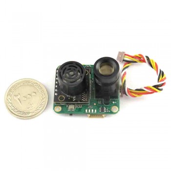
ماژول سنسور جریان نوری PX4FLOW ویژه PIXHAWK

کد انبار : 1302-83-2528
مدل کالا:CUAV-PX4FLOW-V2.1
موجودی: 1
قیمت: 
660,000تومان
 
emad در پنجشنبه 26 آذر 1394 - 22:30:43
5 نظر
ببخشید کار این سنسور چیه؟

پاسخ:
با سلام
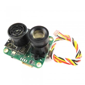
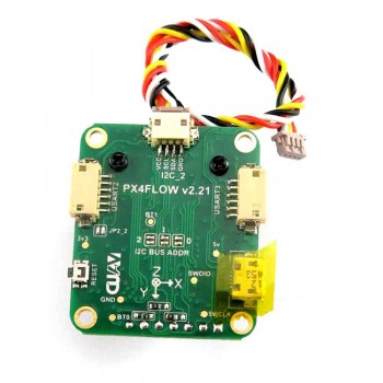
دوست گرامی این ماژول یک دوربین است که در طراحی آن سنسور هم در کنار آن قرار داده شده است که آن را از یک وبکم معمولی تمایز می کند.
اطلاعات کامل را در لینک زیر مشاهده فرمایید:
https://pixhawk.org/modules/px4flow
امیر در سه شنبه 17 آذر 1394 - 09:04:49
5 نظر
با سلام
اینجانب متقاضی این محصول هستم ولی پیش از خرید قصد دارم از کیفیت آن که توسط CUAV تولید می‌شود، اطمینان پیدا کنم. ین محصول توسط توزیع‌کنندگانی مانند ALibaba، Aliexpressو ... توزیع می‌شود ولی اطلاعات فنی لازم توسط آنها ارائه نمی‌شود. درصورت امکان، سایت اصلی سازنده چینی را جهت ارزیابی کیفیت و دریافت کاتالوگ این محصول معرفی نمایید. 
با تشکر فراوان


پاسخ:
با سلام.
تمامی اطلاعات موجود درج شده است .
تاکنون دوستان ، همکاران و سازمانهایی که این کالا را خریداری نموده اند هیچ یک مشکل یا نکته منفی در مورد این کالا بیان نکرده اند.
mohammadi در سه شنبه 31 شهریور 1394 - 09:37:54
5 نظر
سلام بنده خریدار این قطعه هستم اما اصل آمریکایی 3DR Robotic


پاسخ:
با سلام 
این کالا محصول شرکت CUAV چین و البته دارای کیفیت بسیار مطلوبی می باشد.
در صورت تمایلاصرار به تهیه محصول 3DR Robotic از پیش سفارشات اقدام نمایید.
قابل تامین می باشد.
اما توجه داشته باشید از نظر کیفیت تفاوتی با محصول ارائه شده ندارد.فقط قیمت بالاتر است.
  • ShahBaz

آپلود برنامه از طریق برنامه اردوینو به اتمگا8

ShahBaz | يكشنبه, ۲۹ آذر ۱۳۹۴، ۱۱:۰۷ ب.ظ

آپلود برنامه از طریق برنامه اردوینو به اتمگا8x به وسیله پروگرمر پارالل

شهنازی, [۲۰.۱۲.۱۵ ۲۲:۱۵]
So it is possible use the Atmega8, but you need to upload Arduino NG or older w/ ATmega8 bootloader to the chip and check your code (mind the libraries!) for use of hardware that is not present at Atmega8.

To burn the bootloader I am using a Parallel Cabe, like this: http://arduino.cc/en/Hacking/ParallelProgrammer

And follow the sequence below to burn it:

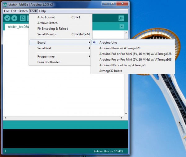
Choose menu Tools > Boards > Arduino NG or older w/ ATmega8
Choose menu Tools > Programmer > Parallel Programmer
Menu Tools > Burn Bootloader
That's it! Regards Renato Aloi

شهنازی, [۲۰.۱۲.۱۵ ۲۲:۱۵]
https://www.arduino.cc/en/Hacking/ParallelProgrammer

  • ShahBaz

بوت لودر آردوینو-زبان اصلی از اردوینو.سی سی

ShahBaz | جمعه, ۲۷ آذر ۱۳۹۴، ۱۱:۱۹ ب.ظ

Burning the Bootloader

To burn the bootloader, you'll need to buy an AVR-ISP (in-system programmer), USBtinyISP or build aParallelProgrammer. The programmer should be connected to the ICSP pins (the 2 by 3 pin header) - make sure you plug it in the right way. The board must be powered by an external power supply or the USB port.

Make sure you have the right item selected in the Tools | Board menu. Then, just launch the appropriate command from the Tools > Burn Bootloader menu of the Arduino environment. Burning the bootloader may take 15 seconds or more, so be patient.

https://www.arduino.cc/en/Hacking/Bootloader?from=Tutorial.Bootloader

  • ShahBaz

ماژول رله 5 ولت

ShahBaz | دوشنبه, ۲۵ آبان ۱۳۹۴، ۱۱:۵۵ ب.ظ

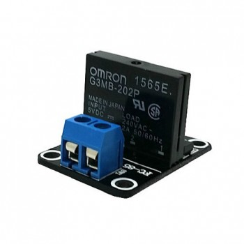
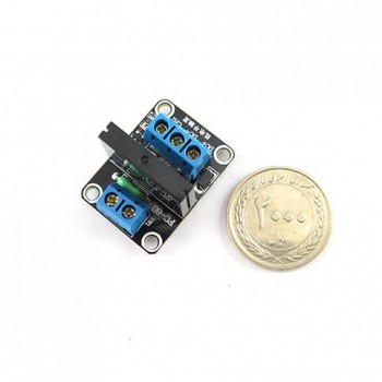
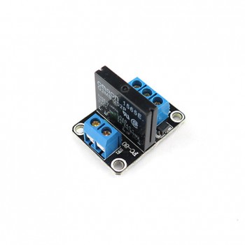
ماژول رله 5 ولت دو کاناله OMRON SSR

کد انبار : 1518-73-2839
مدل کالا:Two-Channel-SSR
موجودی: 5
قیمت: 
16,900تومان
 

ماژول رله 5 ولت دو کاناله OMRON SSR 

5V Omron solid state relay 240V 2A, output with resistive fuse 240V 2A
Description:
Size: 53*33*23mm/2.08*1.31*0.9"
Input Power: 5V DC (160mA)
Input control signal voltage: 
(0-2.5V state low relay OFF) 
(3.3-5V state high relay ON)

Module interface:
Input section:
DC +: positive power supply (by relay voltage power supply)
DC-: connect power negative
CH1: 1 road relay module signal to trigger the end (high level trigger effective)
CH2: 2 road relay module signal to trigger the end (high level trigger effective)


ماژول رله 5 ولت دوکاناله

تولید کننده: SIQMA
کد انبار : 349-73-1310
مدل کالا:RELAY-2CH
موجودی: 4
قیمت: 
6,300تومان
 

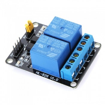
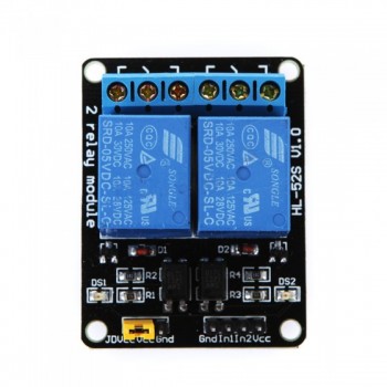
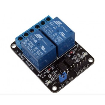
ماژول رله 5 ولت دو کاناله

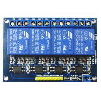
هر یک از پین های آردوینو ولتاژ خروجی5 ولت و حداکثر جریان 40 میلی آمپر را برای شما فراهم می کنند و این مقدار ولتاژ و جریانی که برد آردوینو برای شما فراهم می کند برای راه اندازی بسیاری از وسایل کافی نمی باشد، از همین رو این ماژول گزینه بسیار مناسبی برای کنترل لامپ ها ، موتور ها ، شیر آلات الکترونیکی و یا حتی دستگاه های مختلف و سایر وسایلی است که نیاز به ولتاژ و جریان بالا دارند.با استفاده از این ماژول پرکاربرد در کنار بردهای آردوینو شما می توانید چراغ هاو سایر وسایل متصل به برق شهری منزلتان را خاموش یا روشن کنید، درب منزل را باز نمایید ، با اندکی توسعه در کارگاه یا کارخانه خود دستگاه ها و ماشین آلات خود را به صورت هوشمند و اتوماتیک کنترل نمایید و یا هزاران ایده دیگر در سایر زمینه های خانگی ، صنعتی ، کشاورزی ، سیستم های امنیتی و ... را اجرا نمایید. این ماژول طوری طراحی شده است که پین های دیجیتال برد آردوینو مستقیما به ورودی کنترل رله وصل می شود ، یک LED کوچک روی برد قرار دارد که وضعیت رله را به شما نشان می دهد . در صورتی که رله را به برق شهری (AC) متصل می نمایید ، هر رله نصب شده بر روی ماژول حداکثر 250 ولت و 10 آمپر جریان و چنانچه ولتاژ شما DC باشد حداکثر تا 30 ولت و 10 آمپر جریان را تحمل می نماید.
ورودی فعال ساز رله active low میباشدو این به این معنی است که برای روشن کردن رله بایستی پین خروجی آردوینو را low کرد و برای خاموش کردن رله باید پین خروجی رله را high کرد.

تعداد کانال ها ( رله های نصب شده بر روی برد ) : 2 کانال


برای اطلاعات بیشتر و دریافت نمونه کدهای آردوینو و مثال ها به صفحه مربوط به این ماژول در انجمن مراجعه نمایید


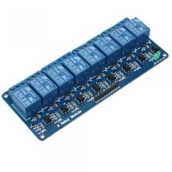
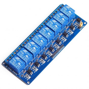
ماژول رله 5 ولت هشت کاناله

تولید کننده: SIQMA
کد انبار : 87-73-1031
مدل کالا:RELAY-8CH
موجودی: 15
قیمت: 
24,800تومان
 

ماژول رله 5 ولت هشت  کاناله

هر یک از پین های آردوینو ولتاژ خروجی5 ولت و حداکثر جریان 40 میلی آمپر را برای شما فراهم می کنند و این مقدار ولتاژ و جریانی که برد آردوینو برای شما فراهم می کند برای راه اندازی بسیاری از وسایل کافی نمی باشد، از همین رو این ماژول گزینه بسیار مناسبی برای کنترل لامپ ها ، موتور ها ، شیر آلات الکترونیکی و یا حتی دستگاه های مختلف و سایر وسایلی است که نیاز به ولتاژ و جریان بالا دارند.با استفاده از این ماژول پرکاربرد در کنار بردهای آردوینو شما می توانید چراغ هاو سایر وسایل متصل به برق شهری منزلتان را خاموش یا روشن کنید، درب منزل را باز نمایید ، با اندکی توسعه در کارگاه یا کارخانه خود دستگاه ها و ماشین آلات خود را به صورت هوشمند و اتوماتیک کنترل نمایید و یا هزاران ایده دیگر در سایر زمینه های خانگی ، صنعتی ، کشاورزی ، سیستم های امنیتی و ... را اجرا نمایید. این ماژول طوری طراحی شده است که پین های دیجیتال برد آردوینو مستقیما به ورودی کنترل رله وصل می شود ، یک LED کوچک روی برد قرار دارد که وضعیت رله را به شما نشان می دهد . در صورتی که رله را به برق شهری (AC) متصل می نمایید ، هر رله نصب شده بر روی ماژول حداکثر 250 ولت و 10 آمپر جریان و چنانچه ولتاژ شما DC باشد حداکثر تا 30 ولت و 10 آمپر جریان را تحمل می نماید.
ورودی فعال ساز رله active low میباشدو این به این معنی است که برای روشن کردن رله بایستی پین خروجی آردوینو را low کرد و برای خاموش کردن رله باید پین خروجی رله را high کرد.

تعداد کانال ها ( رله های نصب شده بر روی برد ) : 8 کانال


برای اطلاعات بیشتر و دریافت نمونه کدهای آردوینو و مثال ها به صفحه مربوط به این ماژول در انجمن مراجعه نمایید


ماژول رله 5 ولت هشت کاناله OMRON SSR

کد انبار : 1514-73-2831
مدل کالا:Eight-Channel-SSR
موجودی: 16
قیمت: 
74,100تومان
 

ماژول رله 5 ولت هشت کاناله OMRON SSR 

Description:
5V Omron solid state relays 240V 2A, output with resistive fuse 240V 2A
Size: 103*53*21mm/4.05*2.08*0.82"
The input power supply: 5V DC (160mA)
The input control signal voltage:
(0-2.5V low state relays OFF)
(3.3-5V state high relay ON )
2.54cm pin and blue KF301 terminals connected to the control line is more convenient

Module interface:
Input section:
DC +: positive power supply (relay voltage power supply)
DC-: connect power negative
CH1: 1 signal to trigger the end of the relay module (High level trigger valid)
CH2: 2-way relay module signal triggering end (High level trigger valid)
CH3: 3 relay module signal triggering end (High level trigger valid)
CH4: 4-channel relay module signal triggering end (High level trigger valid)
CH5: 5-way relay module signal triggering end (High level trigger valid)
CH6: 6-way relay module signal triggering end (High level trigger valid)
CH7: 7-way relay module signal triggering end (High level trigger valid)
CH8: 8-channel relay module signal triggering end (High level trigger valid)


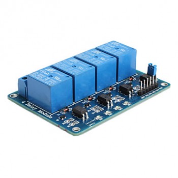
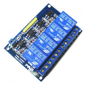
ماژول رله 5 ولت چهار کاناله

تولید کننده: SIQMA
کد انبار : 86-73-1030
مدل کالا:RELAY-4CH
موجودی: در حال حاضر موجود نمی باشد.
[ برای اطلاع از موجودی این کالا در آینده، بر روی دکمه "اضافه به سبد خرید" کلیک کنید]
قیمت: 
12,400تومان
 

ماژول رله 5 ولت چهار  کاناله

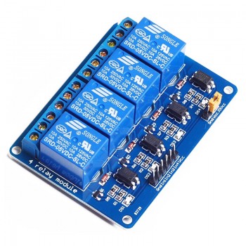
هر یک از پین های آردوینو ولتاژ خروجی5 ولت و حداکثر جریان 40 میلی آمپر را برای شما فراهم می کنند و این مقدار ولتاژ و جریانی که برد آردوینو برای شما فراهم می کند برای راه اندازی بسیاری از وسایل کافی نمی باشد، از همین رو این ماژول گزینه بسیار مناسبی برای کنترل لامپ ها ، موتور ها ، شیر آلات الکترونیکی و یا حتی دستگاه های مختلف و سایر وسایلی است که نیاز به ولتاژ و جریان بالا دارند.با استفاده از این ماژول پرکاربرد در کنار بردهای آردوینو شما می توانید چراغ هاو سایر وسایل متصل به برق شهری منزلتان را خاموش یا روشن کنید، درب منزل را باز نمایید ، با اندکی توسعه در کارگاه یا کارخانه خود دستگاه ها و ماشین آلات خود را به صورت هوشمند و اتوماتیک کنترل نمایید و یا هزاران ایده دیگر در سایر زمینه های خانگی ، صنعتی ، کشاورزی ، سیستم های امنیتی و ... را اجرا نمایید. این ماژول طوری طراحی شده است که پین های دیجیتال برد آردوینو مستقیما به ورودی کنترل رله وصل می شود ، یک LED کوچک روی برد قرار دارد که وضعیت رله را به شما نشان می دهد . در صورتی که رله را به برق شهری (AC) متصل می نمایید ، هر رله نصب شده بر روی ماژول حداکثر 250 ولت و 10 آمپر جریان و چنانچه ولتاژ شما DC باشد حداکثر تا 30 ولت و 10 آمپر جریان را تحمل می نماید.
ورودی فعال ساز رله active low میباشدو این به این معنی است که برای روشن کردن رله بایستی پین خروجی آردوینو را low کرد و برای خاموش کردن رله باید پین خروجی رله را high کرد.

تعداد کانال ها ( رله های نصب شده بر روی برد ) : 4 کانال


برای اطلاعات بیشتر و دریافت نمونه کدهای آردوینو و مثال ها به صفحه مربوط به این ماژول در انجمن مراجعه نمایید

ماژول رله 5 ولت چهار کاناله OMRON SSR

کد انبار : 1516-73-2836
مدل کالا:Four-Channel-SSR
موجودی: 18
قیمت: 
37,400تومان
 

ماژول رله 5 ولت چهار کاناله OMRON SSR

Description:
1, OMRON 5V 240V solid state relay 2A output with resistance type fuse 240V 2A.
2, size: 57*55*25 (length * width * height) net weight: 40g
3, the input power supply: 5V DC (160MA)
4, the input control signal voltage:
(0-2.5V the state of low level relay ON)
(3.3-5V high level relay OFF)
5, the 2.54CM pin and blue KF301 terminal is connected to the line of control more convenient.

Module interface:
Input part:
DC+: connect the power supply positive (press the relay voltage power supply)
DC-: the cathode of a power supply
CH1: 1 relay module signal trigger end (low level trigger effective)
CH2: 2 relay module signal trigger end (low level trigger effective)
CH3: 3 relay module signal trigger end (low level trigger effective)
CH4: 4 relay module signal trigger end (low level trigger effective)

High level and low level of meaning:
High level trigger refers to the signal trigger end (IN) had a positive voltage and the negative pole of the power supply is usually between, and the triggering end of a trigger connected with the positive pole of a power supply, when the trigger end has a positive voltage or reached the trigger voltage, the relay is attracted.
Low level trigger refers to the signal triggering voltage between the end and the negative electrode of the power supply is OV, or trigger terminal voltage lower voltage than the positive power supply voltage, low to can trigger, make the relay, is usually the cathode of the power supply and the triggering end of a trigger mode connection, so that the relay is attracted.

Electrical parameters:
The static current voltage version of the working current of trigger voltage, trigger current
1 way 5V 0mA 13.8mA 0-2.5V 2mA
2 way 5V 0mA 26.8mA 0-2.5V 2mA
3 way 5V 0mA 37mA 0-2.5V 2mA
4 way 5V 0mA 48mA 0-2.5V 2mA

ماژول رله 5 ولت یک کاناله

کد انبار : 801-73-1881
مدل کالا:RELAY-1CH-5V
موجودی: 22
قیمت: 
5,400تومان
 

ماژول رله 5 ولت یک کاناله

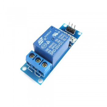
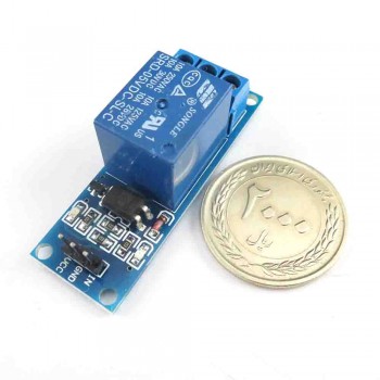
هر یک از پین های آردوینو ولتاژ خروجی 5 ولت و حداکثر جریان 40 میلی آمپر را برای شما فراهم می کنند و این مقدار ولتاژ و جریانی که برد آردوینو برای شما فراهم می کند برای راه اندازی بسیاری از وسایل کافی نمی باشد، از همین رو این ماژول گزینه بسیار مناسبی برای کنترل لامپ ها ، موتور ها ، شیر آلات الکترونیکی و یا حتی دستگاه های مختلف و سایر وسایلی است که نیاز به ولتاژ و جریان بالا دارند.با استفاده از این ماژول پرکاربرد در کنار بردهای آردوینو شما می توانید چراغ هاو سایر وسایل متصل به برق شهری منزلتان را خاموش یا روشن کنید، درب منزل را باز نمایید ، با اندکی توسعه در کارگاه یا کارخانه خود دستگاه ها و ماشین آلات خود را به صورت هوشمند و اتوماتیک کنترل نمایید و یا هزاران ایده دیگر در سایر زمینه های خانگی ، صنعتی ، کشاورزی ، سیستم های امنیتی و ... را اجرا نمایید. این ماژول طوری طراحی شده است که پین های دیجیتال برد آردوینو مستقیما به ورودی کنترل رله وصل می شود ، یک LED کوچک روی برد قرار دارد که وضعیت رله را به شما نشان می دهد . در صورتی که رله را به برق شهری (AC) متصل می نمایید ، هر رله نصب شده بر روی ماژول حداکثر 250 ولت و 10 آمپر جریان و چنانچه ولتاژ شما DC باشد حداکثر تا 30 ولت و 10 آمپر جریان را تحمل می نماید.
ورودی فعال ساز رله active low میباشدو این به این معنی است که برای روشن کردن رله بایستی پین خروجی آردوینو را low کرد و برای خاموش کردن رله باید پین خروجی رله را high کرد.


تعداد کانال ها ( رله های نصب شده بر روی برد ) : 1 کانال

ماژول رله 5 ولت یک کاناله OMRON SSR

کد انبار : 1190-73-2397
مدل کالا:A03B 
موجودی: 60
قیمت: 
9,900تومان
 

ماژول رله 5 ولت یک کاناله OMRON SSR

Product Details:
Solid State Relay Module
Size: approx. 25 x 34 x 25mm, net weight: 13g
5v solid-state relay 240v 2a , the output resistance fuse is 240v 2a.
Input voltage: 5v dc (160ma)
Input voltage control signal: (0-1.5V low level, relay ON), (2.5-5V high level, relay OFF)
Quiescent current: 0MA
Trigger voltage: 0-1.5v
Trigger current: 2ma

Module interface:
The positive (DC + : connect power according to the relay voltage power supply)
DC - : connect power negative
CH: relay module (effective) low level trigger signal trigger end

High level and low level meaning:
High level refers to the trigger signal trigger terminal (IN) and negative between a power source
A forward voltage, usually with the power of the positive and trigger a client connection
Kind of trigger mode, when the trigger side has the positive voltage or trigger voltage, relay is off.
Low level trigger refers to signal triggering end between the cathode voltage and power
For OV, or trigger voltage lower than positive voltage,
Low enough to trigger voltage, relay, absorption is often will power
The negative connection way of a trigger and trigger the end, the relay is off.


  • ShahBaz

Bootload an ATmega328 Microcontroller

ShahBaz | يكشنبه, ۲۶ مهر ۱۳۹۴، ۰۴:۱۶ ب.ظ

Bootload an ATmega328 Microcontroller

Bootloading Configuration

Bootloading Configuration

This page adds to any of the Arduino on a Breadboard projects out there – there are a number of great resources on building your own Breadboard-based Arduino. I have documented my own (see here), which I used for various projects. I then found that I was struggling to program some of the boards I made, usually when I switched suppliers. After some investigation, I found that:

1. Not all suppliers provide microcontrollers with a Bootloader (even though they may say they do)

2. Not all ATmega328s are equal

A bootloader, simply put, is a programme that sits on the chip and manages the upload of your sketches onto the chip. There are plenty of bootloading resources out there, but I struggled to find a single one that pulled everything together in a way that made sense to me. Here is the process that I followed.

Step 1: The parts


Step 2: The Approach

We’re going to use the Arduino UNO to bootload the ATmega328 that is sitting on the Arduino-on-a-Breadboard. This is fairly straightforward if you have an ATmega328P-PU, but needs an extra step for an ATmega328-PU. I’ll tackle the differences later on.

Step 3: Program your Arduino UNO as an ISP

The Arduino ISP Sketch

The Arduino ISP Sketch

We need to program the Arduino UNO to act as a an ISP (In-System Programmer), so that it can burn the bootloader onto the Breadboard chip.

  1. Open the Arduino IDE
  2. Open the ArduinoISP sketch (under File, Examples)
  3. If you’re using version 1.0 of the IDE:
    • search for “void heartbeat”
    • Change the line that reads:
    • delay(40); to delay(20);
  4. Connect your UNO to the PC, making sure it’s not connected to the Arduino on a Breadboard.
  5. Ensure your UNO is selected under the Boards menu option, and upload the sketch.

Step 4: Connect your ATmega328P

Bootloading Connections

Bootloading Connections

The ATmega328 pin mapping

The ATmega328 pin mapping

Now connect your ATmega to your UNO as follows:

  • UNO 5v —> ATmega pin 7 (VCC)
  • UNO GND —> ATmega pin 8 (GND)
  • UNO pin 10 —> ATmega pin 1 (RESET)
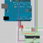
  • UNO pin 11 —> ATmega pin 17 (MOSI)
  • UNO pin 12 —> ATmega pin 18 (MISO)
  • UNO pin 13 —> ATmega pin 19 (SCK)

Make sure that you don’t have anything else connected to the ATmega pins used above.

Step 5: Which ATmega328 are you using?

The ATmega328P-PU

The ATmega328P-PU

I learnt the hard way that there is more than one type of ATmega328. The two variants that are of interest to us are the ATmega328-PU and theATmega328P-PU.

To decode the naming conventions:

  •  -PU means that the chips are in a PDIP package, the format we need for our breadboard.
  • The 328P is a picoPower processor, designed for low power consumption, and is the chip used on the Arduino boards.

The 328 does not have picoPower technology, and is not used on the Arduino boards – as a result it is not explicitly supported by the Arduino IDE.

What this means is that we can easily bootload the ATmega328P, but not the ATmega328. This was a problem for me, as I had bought a load of ATmega328-PU chips from a supplier that had listed them at ATmega328P-PU.

Workaround: Scroll to the end of this page if you need the workaround to get the ATmega328-PU working.

Step 6: Bootload the ATmega328

To bootload your chip, open the Arduino IDE:

From the Tools menu:

  • under the Board option choose Arduino UNO
  • under the Serial Port option ensure the correct port is selected
  • under the Programmer option choose Arduino as ISP

To burn the Bootloader, choose Burn Bootloader from the Tools menu.

You should see a message “Burning bootloader to I/O Board (this may take a minute)”

Burning the Bootloader

Burning the Bootloader

Once the bootloader has been burned, you’ll see a message confirming the success.

Bootloader Burning Done

Bootloader Burning Done

Congratulations: You’re now ready to load sketches onto your ATmega microcontroller!

Workaround for the ATmega328-PU

If you try to bootload an ATmega328-PU, you’ll get a message something along the lines of:

avrdude: Device signature = 0x1e9514

avrdude: Expected signature for ATMEGA328P is 1E 95 0F

Double check chip, or use -F to override this check.

You could also get a more exciting version:

avrdude: Yikes! Invalid device signature.

Yikes AVRDude Error

Yikes! AVRDude Error

What does this all mean?

Each microcontroller has a signature – a unique code that identifies its model. When you bootload a chip (or even upload a sketch) the Arduino IDE checks that the chip selected matches the type it’s connected to – this is to protect the mcrocontroller from user error – if this check wasn’t in place and you accidentally select the wrong controller in the IDE and burn the bootloader you could “brick” your controller.

Even though the ATmega328-PU in essence functions in the same way as the ATmega328P-PU, it has a different signature, and one that isn’t recognised by the Arduino IDE. (Behind the Scenes: The Arduino IDE actually uses a utility called AVRDUDE to programme the chips, so you’ll see error messages from avrdude. (Adafruit have a good tutorial on avrdude)


The ATmega328 Bootloading Workaround

Find and open the folder that the Arduino IDE is installed in, then:

  •  open the subfolder ..\hardware\tools\avr\etc
  • Make a backup copy of the file avrdude.conf
  • Open the file avrdude.conf in a text editor – I use the cross-platform Geany as it formats the file better than Notepad.
  • Search for: 0x1e 0x95 0x0F (this is the ATmega328P signature)
  • Replace it with: 0x1e 0x95 0x14 (this is the ATmega328 signature)
  • Save the file
  • Restart the Arduino IDE
  • Continue with the rest of the steps, and once bootloading is complete restore the backup copy you made.

You are now good to bootload ATmega328-PU microcontrollers as well!

Note: A number of people, including myself, have tried to add an ATmega328 entry into the avrdude.conf and boards.txt. This process will allow you to use avrdude from the command-line (quite daunting), but the Arduino IDE will not compile.

Uploading Sketches

ATmega328P-PU
You can leave your setup as it is, and use the Arduino UNO to upload sketches to your newly bootloaded ATmega (File, Upload using Programmer).
ATmega328-PU
The IDE will notice that the signature isn’t valid – so you’ll have to either alter the avrdude.conf file again or use an FTDI board to upload. I prefer using an FTDI board anyway as it doesn’t take my UNO out of circulation and is quicker to connect.

  • ShahBaz

دانلود آردوینو 1.0.5

ShahBaz | يكشنبه, ۲۶ مهر ۱۳۹۴، ۰۸:۴۷ ق.ظ
download arduino1.05
دانلود آردوینو 1.0.5 
حجم: 52 مگابایت


مسیر فایل های  hardware و libraries

C:\Users\Ehsan\Documents\Arduino

از مسیر file=> prefrence می توان فهمید فایل های مروبط به کتابخانه و اسکتچ را کجا ریخت. عموما مسیر بالا هست.
  • ShahBaz

روش پروگرام کردن بوت لودر arduino

ShahBaz | شنبه, ۲۵ مهر ۱۳۹۴، ۰۹:۰۸ ب.ظ

روش پروگرام کردن بوت لودر arduino

روش پروگرام کردن بوت لودر arduino

برای نوشتن بوت لودر آردوینو دو روش وجود دارد:

۱٫ روش اول با استفاده از برد های Arduino که معمولا برد Uno می باشد که در این سایت یه آموزش با میکروکنترلر ATmega8 گذاشته ام.

۲٫ روش دوم با استفاده از پروگرامرهای SPI میباشد که من با STK500 و AVR Studio 4 این کار را انجام داده ام و آموزش آن را به صورت تصویری در زیر می توانید ببینید.

http://turbodigital.ir/?p=40


  • ShahBaz

بوت لودر ATmega8 در Arduino

ShahBaz | شنبه, ۲۵ مهر ۱۳۹۴، ۰۸:۲۸ ب.ظ

ATmega8 bootloader in arduino

بوت لودر ATmega8 در Arduino

به همره قسمت خطایابی در انتهای همین مطلب

به نام خدا

همان طور که می دانید در بردهای Arduino برد Atmega8 وجود ندارد ولی این امکان وجود دارد با نوشتن یک بوت لودر در ATmega8 به راحتی با این میکروکنترلر در Arduino برنامه نویسی کرد. حالا من آموزش کاملی رو واستون می ذارم.

ابتدا مواد لازم:

۱. Arduino ورژن ۱٫۰٫۵ (من با این ورژن تست زدم ولی احتمالا بالاتر هم جواب بده)

۲.ATmega8A-PU (نگران نباشید با دیگر سری ها هم جواب می دهد ولی واسه شروع از این استفاده کنید که شک یا شبه ایی پیش نیاد)

۳. دو/۲ عدد برد Arduino Uno (اول به این شکل انجام بدید تا حساب کار دستتون بیاد بعد برید روی Breadboard)

http://www.4shared.com/rar/GMfMPXrkce/ATmegaBOOT-prod-firmware-2009-.html

اول از هر کاری به مسیر hardware/arduino/bootloaders/atmega8 بروید سپس بررسی کنید فایل ATmegaBOOT-prod-firmware-2009-11-07.hex در فولدر جاری باشد اگر نبود فایل رو از لینک بالا دانلود کنید و در مسیر فوق کپی کنید و بعد از حالت فشرده خارج کنید.

سپس در لینک زیر فایل فشرده رو دانلود کنید سپس از حالت فشرده خارج کنید و دو تا فایل pins_arduino.h و pins_arduino.c رو در مسیر hardware/arduino/cores/arduino کپی کنید.

http://www.4shared.com/rar/MnaI7s-Eba/pins_arduino.html

خوب حالا می رویم سراغ سخت افزار ها. دو عدد برد Arduino Uno یکی رو اول به کامپیوتر وصل کنید و سپس Arduino رو اجرا کنید و مطابق عکس برد Arduino Uno رو انتخاب کنید و بعد پورت سریال رو هم انتخاب کنید.

bootloader (1)

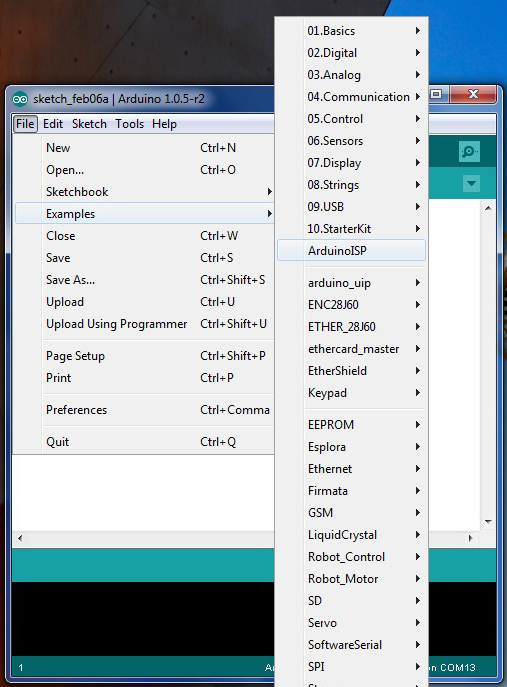
حالا مطابق عکس پایین در نوار ابزار بر روی File کلیک کنید و سپس در Examples بر روی ArduinoISP کلیک کنید حالا برنامه رو Upload کنید.

bootloader (2)

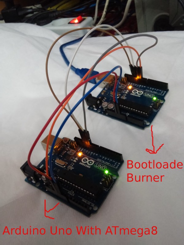
الان Bootloader Burner آماده است. خوب حالا برد Arduino Uno بعدی رو باید میکروکنترلر ATmeag328P رو از روش بردارین و یک ATmega8 جایگزین کنید.نگران نباشد چون ترتیب پایه های ATmega328P و ATmega8 دقیقا مثل هم هستند. بعد از انجام این کار دقیقا مطابق عکس پایین اتصالات رو برقرار می کنید.اما قبل به مسیر Arduino/hardware/arduino برید و  فایل boards.txt باز کنید. دنبال Arduino NG or older w/ ATmega8 بگردید حالا باید فیوز بیت های میکرو رو نتظیم کنید دو تا خط مثل زیر واسه میکرو تعریف شده

atmega8.bootloader.low_fuses=0xdf
atmega8.bootloader.high_fuses=0xca
بایت کم ارزش روی df و پر ارزش روی ca تنظیم کنید از آدرس Engbedded AVR Fuse Calculator هم می توانید استفاده کنید.

bootloader (3)


Bootloader Burner                            Arduino Uno With ATmega8

۵V+ ========================> +5V

GND ========================> GND

SCK =========================> SCK  پایه 13

MISO ========================> MISO  پایه 12

MOSI ========================> MOSI  پایه 11

SS ========================> Reset  پایه 10


*پایه Reset در بخش پاور برد آردوینو قبل از پایه 3.3 ولت هست.


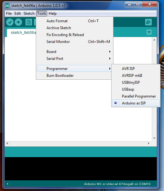
خوب حالا بعد از اتصالات می ریم سراغ نوشتن بوت لودر. ابتدا کابل USB رو به بردی که به عنوان Bootloader Burner آماده کردیم متصل می کنیم و مطابق عکس پایین Programmer رو بر روی Arduino as ISP قرار می دهیم.

bootloader (4)

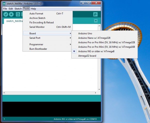
و بعد مطابق عکس پایین برد Arduino NG or order w/ATmega8 رو انخاب می کنیم و بعد در نوار ابزار بر روی Tools کلیک کنید و بروی Burn Bootloader کلیک کنید. LED های TX و RX بر بروی برد Arduino Uno که به عنوان Bootloader Burner آماده شده روشن می شوند و خاموش می شوند و بعد از زمان خیلی کوتاه دوباره روشن می شوند و عملیات نوشتن Bootloader آغاز می شود. و با پیغام تکمیل شدن نوشتن بوت لودر توسط کامپایلر به پایان می رسد.

bootloader (5)

حالا کابل USB رو به بردی که ATmeag8 رو جایگزین کردید متصل کنید و بعد پروژه چراغ چشمک زن رو Upload کنید و لذت ببرید.


خطاها:

سلام
من طبق کارهای شما پیش رفتم ولی موقع پروگرام کردن خطای

“efuse” memory type not defined for part “ATMEGA8″
میده
مشکل از چیه؟
در ضمن من از نسخه ۱٫۵٫۶ اردوینو استفاده میکنم.
با تشکر

-----------------------------------------------------------------------------------------------------------

سلام دوباره
من اردوینو ۱٫۰۵ رو نصب کردم اما اینبار خطای

core.a(main.cpp.o): In function main':C:\Program Files\Arduino\hardware\arduino\cores\arduino/main.cpp:11: undefined reference to setup’
C:\Program Files\Arduino\hardware\arduino\cores\arduino/main.cpp:14: undefined reference to `loop’

رو میده…


پاسخ:

باید در نوار ابزار بر روی Tools کلیک کنید و بروی Burn Bootloader کلیک کنید. احتمالا شما روی Upload کلیک کرده اید.

-----------------------------------------------------------------------------------------------------------


سلام مجدد؛
بعد از باز و بستن برنامه همه چیز به خوبی پیش رفت و بوت لودر آپلود شد.

فقط یه نکته و اونم اینکه بعد از اینکه برد آنو با میکرو اتمگ ۸ بوت شد از این به بعد برای ریختن برنامه داخل اون باید در قسمت “برد” به جای “اردوینو انو” باید گزینه “Arduino NG or order w/ATmega8 ” رو انتخاب کرد.

مدت زمان بوت شدن برنامه ال ای دی چشمک زن در این بردها ممکن هست نسبت به بردهای اردوینو با اتمگ 328 بیشتر باشه..مثلا شاید توی اتمگ328 بلافاصله بعد از آپلود برنامه چشمک زن ال ای دی شروع به چشمک زدن بکنه اما توی اتمگ 8 یه چند ثانیه ای تاخیر داشته باشه...که زیاد مهم نیست.


دقت شود بعد از اینکه بوت لودر داخل برد آردوینو با اتمگ 8 ریختید؛، دقت کنید که سیم های +5 و زمین و پایه ریست رو حتمن خارج کنید. و بعد برنامتون رو بریزید در غیر این صورت با خطا مواجه میشید.


با تشکر


منبع:

http://turbodigital.ir/?p=57

  • ShahBaz