ماژول +NRF24L01 - برد SMD
کد انبار : 901-119-2026
مدل کالا:NRF24L01P-SMD
موجودی: 2
TANHA71 در پنجشنبه 28 خرداد 1394 - 14:35:20
با سلام ، ماژول جمع جور و با کیفیتی هست و خدایش ارزش خرید داره. خب من پایه هاش را می نویسم که دوستان باهاش مشکل پیدا نکنن!
روی برد از پایه 1 " به رنگ سفید نوشته شده"
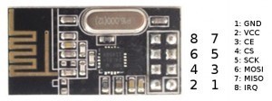
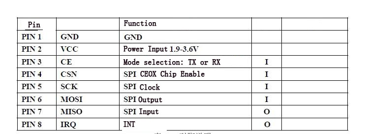
پایه 1= VCCکه باید به 3.3 ولت وصل بشه و نه بیشتر. پایه 2= GND و پایه 3=CE و پایه 4=CSN=CS پایه 5=CLK=SCKو پایه 6 =DAT=MOSI و پایه 7 = MISOو چایه 8= IRQ
Pin connections:
DR1 -> 2 (digital pin 2)
CE -> 3
CS -> 4
CLK -> 5
DAT -> 6
علیرضا در سه شنبه 04 آذر 1393 - 22:48:04
با سلام
برد این ماژول چقدر است؟
غلامحسین بغدادپور در دوشنبه 05 آبان 1393 - 09:08:05
من راه اندازیش کردم؛بی نظیره ...
پاسخ: سلام خوشحال می شویم اطلاعات خودتون رو در انجمن ب دوستان به اشتراک بذارید
در این آموزش سعی میکنم تا هر چیزی که در مورد این فرستنده وگیرنده میدونم در اختیارتون بزارم تا استاد های محترم به تونند به من کمک کنند
این فرستنده ها یک نوع فرستنده قوی هستند که دیتا لاس کمتری دارند یعنی اطلاعات ازدست رفته کمتری دارند به طور خلاصه اگه به همدیگه کانکت بشن دیگه هیچ اطلاعاتی ازبین نمیره . اما شاید برای شما هم این سوال بیش اومده که برد این نوع فرستنده ها یا گیرنده ها چقدر هست در جواب باید یگم که اگر خوب تقویت بشن (با استفاده از مدارات تقویت کننده )حداکثر بردی که میتونن داشته باشن اونم تویک فضای باز که باد نباشه ۱۸۰۰ متر در نوع برد ایرانی هست.
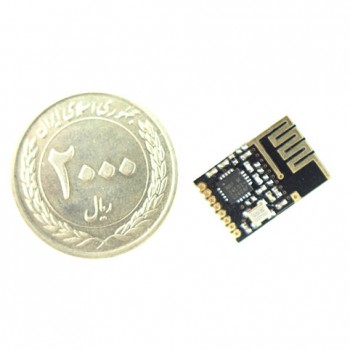
بردهای دیگری هم هستند که توی فروشگاه های اینترنتی کمترین برد در فضای باز رو ۱۰۰ متر تعیین کردن که با تستهای من بردش به این حدود میرسه البته تو یه فضای باز که باد هم نوزه! تست دیگه من این بود که یکی از این بردها رو تو گوشه یه اتاق درست ته خونه گذاشتم که ۳تا دیوار داشت تا حدود ۱۵ متر رو جواب داد این برد به شکل زیر هست

ماژول دیگری هم هست که بردش ۱۱۰۰ متر هست شکلش هم به صورت زیر

اولی حدود۷تومن دومی هم حدود ۳۵ تومن هستش. اینها مباحث در مورد انتخاب ماژول مناسب برای پروژم بودچ
نحوه راه اندازی راه اندازی ماژول NRF24L01 با بسکام:
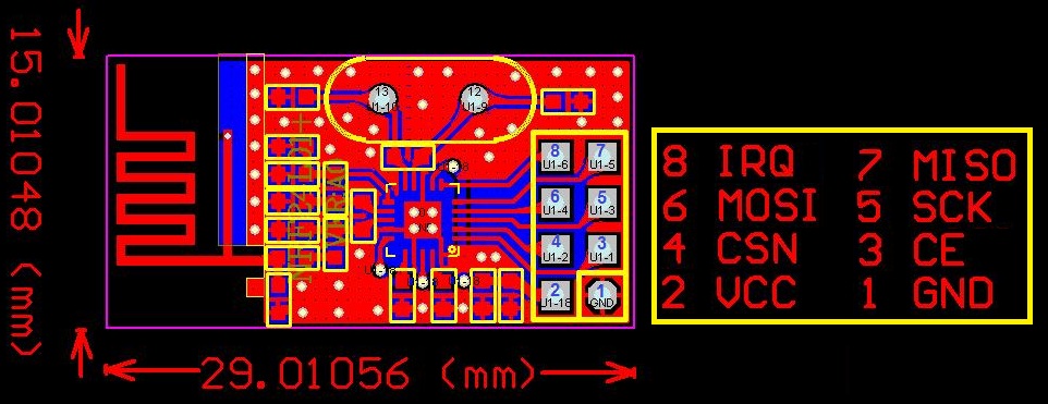
خوب باید در اول توضیح بدم که ما یک ماژول داریم که هم میتونه به صورت فرستنده وهم به صورت گیرنده کار کنه برای شروع باید ابتدا نام پایه ها رو بدونید تا با هاش کار کنید شکل زیر نام پایه ها وترتیبشون رو نششون میده
نحوه تنظیم به عنوان گیرنده:
برای اینکار باید پین شماره 2 رو ۱ کنید یعنی ۳٫۳ولت یا ۵ ولت بشه(این نکته را یاد آور شوم که این ماژول تحمل ۵ ولت را رویه پایه های دیتا دارد ولی باید حتما حتما ولتاژ تغذیه ۳ولت باشه نه بیشتر)
PIN CE=1
BIT : PWR_UP=1 IN CONFIG REGISTER
BIT :PRIM_RX=1
نحوه تنظیم به عنوان فرستنده:
طبق دیتا شیت این ماژول نباید این ماژول بیشتر از ۴میلی ثانیه در مد فرستنده باشه!!!!من که نفهمیدم واسه چی حالا بیخیال این تنضیمات واسه مد فرستنده هست
PIN CE=1
BIT : PWR_UP=0 IN CONFIG REGISTER
BIT :PRIM_RX=1
شوخی کردم که گفتم نمیفهمم راستش اگه تو حافظه انتقال اطلاعات اگه چیزی نباشه به استند بای میره که دوتا استند بای داره حالا نمیخوام قضیه رو برای شما پیچیدش کنم.

میریم واسه تنظیمات دیتا ریت یا نرخ داده ارسالی این ماژول:
برای تنظیم نرخ داده باید تو۲مگابیت بر ثانیه بایدرجیستر زیر به اینگونه تنظیم بشه
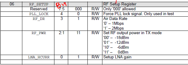
06==H0F=00001111 2 MB/S AND LNA GAIN IS ON
06==H07=00000111 1 MB/S AND LNA GAIN IS ON
در این رجیستر میتوان قدرت ارسال داده را نیز تغیر داد یعنی افزایش یا کاهش داد من تا حالا با صفر دسی بل کار کردم ولی فکر میکنم با افزایش میزان دسی بل بتوان برد این ماژول را افزایش داد اگر میخواهی به جای کد هگز بالا از کد هگز پایین استفاده کنید که میزان دسی بل برابر ۱۸ است:
06==00001001=H09هر یک از این ماژول ها میتوانند با ۶ دستگاه دیگر ارتباط برقرار کنندبه طور همزمان که من به این توضیحات اکتفا میکنم هرچند کم هست ولی من سعی کردم مشکل اساسی افراد در قدرت ارسال و برد و نحوه تنضیم به عنوان گیرنده وفرستنده رو تو این آموزش کوچک براتون بگم من نمونه برنامه راه اندازی این ماژول با بسکام رو از اینترنت پیدا کردم ولی خیلی مبهم هست پس به توضیح این برنامه شروع میکنم:
کدهای برنامه به صورت زیر هست:
دقت کنید این برنامه هم برای گیرنده و هم برای فرستنده هست که فقط با ست یا ریست کرده یک پایه از میکرو . میکر. به فرستنده یا گیرنده تبدیل میشود بدون اینکه برنامه ریزی مجدد انجام بدید در ضمن در این برنامه از اینتراپت میکرو استفاده نشده ودنبال اینتراپت نگردید:
قسمت ۱ کد های راه اندازی ماژول NRF24L01 با بسکام:
قسمت 1
$regfile = "M8def.dat"
$crystal = 8000000
$hwstack = 40
$swstack = 20
$framesize = 40

'=== Declare sub routines
Declare Sub R_register(byval Command As Byte , Byval C_bytes As Byte)
Declare Sub W_register(byval C_bytes As Byte)

'=== Constante ===
'Define nRF24L01 interrupt flag's
Const Idle_int = &H00                                       'Idle, no interrupt pending
Const Max_rt = &H10                                         'Max #of Tx Retrans Interrupt
Const Tx_ds = &H20                                          'Tx Data Sent Interrupt
Const Rx_dr = &H40                                          'Rx Data Received
'SPI(nRF24L01) commands
Const Read_reg = &H00                                       'Define Read Command To Register
Const Write_reg = &H20                                      'Define Write Command To Register
Const Rd_rx_pload = &H61                                    'Define Rx Payload Register Address
Const Wr_tx_pload = &HA0                                    'Define Tx Payload Register Address
Const Flush_tx = &HE1                                       'Define Flush Tx Register Command
Const Flush_rx = &HE2                                       'Define Flush Rx Register Command
Const Reuse_tx_pl = &HE3                                    'Define Reuse Tx Payload Register Command
Const Nop_comm = &HFF                                       'Define No Operation , Might Be Used To Read Status Register
'SPI(nRF24L01) registers(addresses)
Const Config_nrf = &H00                                     'Config' register address
Const En_aa = &H01                                          'Enable Auto Acknowledgment' register address
Const En_rxaddr = &H02                                      'Enabled RX addresses' register address
Const Setup_aw = &H03                                       'Setup address width' register address
Const Setup_retr = &H04                                     'Setup Auto. Retrans' register address
Const Rf_ch = &H05                                          'RF channel' register address
Const Rf_setup = &H06                                       'RF setup' register address
Const Status = &H07                                         'Status' register address
Const Observe_tx = &H08                                     'Observe TX' register address
Const Cd = &H09                                             'Carrier Detect' register address
Const Rx_addr_p0 = &H0A                                     'RX address pipe0' register address
Const Rx_addr_p1 = &H0B                                     'RX address pipe1' register address
Const Rx_addr_p2 = &H0C                                     'RX address pipe2' register address
Const Rx_addr_p3 = &H0D                                     'RX address pipe3' register address
Const Rx_addr_p4 = &H0E                                     'RX address pipe4' register address
Const Rx_addr_p5 = &H0F                                     'RX address pipe5' register address
Const Tx_addr = &H10                                        'TX address' register address
Const Rx_pw_p0 = &H11                                       'RX payload width, pipe0' register address
Const Rx_pw_p1 = &H12                                       'RX payload width, pipe1' register address
Const Rx_pw_p2 = &H13                                       'RX payload width, pipe2' register address
Const Rx_pw_p3 = &H14                                       'RX payload width, pipe3' register address
Const Rx_pw_p4 = &H15                                       'RX payload width, pipe4' register address
Const Rx_pw_p5 = &H16                                       'RX payload width, pipe5' register address
Const Fifo_status = &H17                                    'FIFO Status Register' register address
'Various
Const True = 1
Const False = 0
قسمت ۲:
'=== Config hardware ===
Config Spi = Hard , Interrupt = Off , Data Order = Msb , Master = Yes , Polarity = Low , Phase = 0 , Clockrate = 4 , Noss = 1
'Software SPI is NOT working with the nRF24L01, use hardware SPI only, but the SS pin must be controlled by our self
Config Pinb.1 = Output                                      'CE pin is output
Config Pinb.2 = Output                                      'SS pin is output
Config Pinb.0 = Input                                       'IRQ pin is input
Config Pinc.3 = Input                                       'TX/RX Device _select
Config Portc.4 = Output
Ce Alias Portb.1
Ss Alias Portb.2
Irq Alias Pinb.0
Txrx_device Alias Pinc توسط این پایه میکرو گیرنده یا فرستنده میشود
Spiinit                                                     'init the spi pins
Set Ce
Waitms 10                                                   'Wait a moment until all hardware is stable
Reset Ce                                                    'Set CE pin low
Reset Ss                                                    'Set SS pin low (CSN pin)
Dim D_bytes(33) As Byte , B_bytes(33) As Byte               'Dim the bytes use for SPI, D_bytes = outgoing  B_bytes = Incoming
Dim Temp As Byte , W As Word
Dim Packet_count As Byte


If Txrx_device = True Then Goto Main_tx                     'Is this the RX or TX device?
قسمت سوم:
'===Main rx==========================================================================================================================
Main_rx:
Call R_register(status , 1)                                 'Read STATUS register

Reset Ce                                                    'Set CE low to access the registers
Gosub Setup_rx                                              'Setup the nRF24L01 for RX
Waitms 2                                                    'Add a delay before going in RX
Set Ce                                                      'Set nRF20L01 in RX mode
Do                                                          'Main loop for RX
If Irq = 0 Then                                             'Wait until IRQ occurs, pin becomes low on interrupt
    Reset Ce                                                'Receiver must be disabled before reading pload
    Do                                                      'Loop until all 3 fifo buffers are empty
      Call R_register(rd_rx_pload , 5)                      'Read 5 bytes RX pload register
      Select Case B_bytes(5)
      Case 2 : Set Portc.4
      Case Else : Reset Portc.4
      End Select
      'Print "Pload  : " ; Hex(b_bytes(1)) ; Hex(b_bytes(2)) ; Hex(b_bytes(3)) ; Hex(b_bytes(4)) ; Hex(b_bytes(5))       'Print the pload
      Call R_register(fifo_status , 1)                      'Read FIFO_STATUS
    Loop Until B_bytes(1).0 = True                          'Test or RX_EMPTY bit is true, RX FIFO empty
    D_bytes(1) = Write_reg + Status                         'Reset the RX_DR status bit
    D_bytes(2) = &B01000000                                 'Write 1 to RX_DR bit to reset IRQ
    Call W_register(2)
    Set Ce                                                  'Enable receiver again
   Waitms 2
End If
'Gosub Dump_registers                                        'Unremark me for debugging
Loop
Return
قسمت چهارم:
'===Main tx==========================================================================================================================
Main_tx:
'Print "TX_device"                                           'Send to terminal who i'm
D_bytes(1) = Flush_tx                                       'Flush the TX_fifo buffer
Call W_register(1)
D_bytes(1) = Write_reg + Status                             'Reset the IRQ bits
D_bytes(2) = &B00110000
Call W_register(2)
Do                                                          'Main loop for TX
Incr Packet_count                                           'Increase the send packet counter, for test only
If Packet_count > 254 Then Packet_count = 0
Gosub Setup_tx                                              'Setup the nrf240l01 for TX
D_bytes(1) = Wr_tx_pload                                    'Put 5 bytes in the TX pload buffer
D_bytes(2) = &HAA                                           'Byte 1
D_bytes(3) = &HBB                                           'Byte 2
D_bytes(4) = &HCC                                           'Byte 3
D_bytes(5) = &H11                                           'Byte 4
D_bytes(6) = 2                                              'Byte 5 will be increase every loop
Call W_register(6)                                          'Write 6 bytes to register
Waitms 2
Set Ce                                                      'Set CE for a short moment to transmit the fifo buffer
Waitms 1                                                    '
Reset Ce                                                    '
Waitms 100                                                  'Some delay to read the output on the terminal, line can be removed for max. speed
W = 0                                                       'Counter for time out
Do
   If Irq = 0 Then
       Call R_register(status , 1)
       Temp = B_bytes(1) And &B01110000                     'Mask the IRQ bits out the status byte
      Select Case Temp                                      'Which IRQ occurs
        Case Max_rt                                         'MAX_RT
            'Print "Maximum number of TX retries, Flussing the TX buffer now !"
            D_bytes(1) = Flush_tx                           'Flush the TX buffer
            Call W_register(1)
            D_bytes(1) = Write_reg + Status
            D_bytes(2) = &B00010000                         'Clear the MAX_RT IRQ bit
            Call W_register(2)
            Exit Do
        Case Tx_ds                                          'TX_DS
            'Print "Packet " ; Packet_count ; " send and ACK received."
            D_bytes(1) = Write_reg + Status
            D_bytes(2) = &B00100000                         'Clear the TX_DS IRQ bit
            Call W_register(2)
            Exit Do
        Case Else                                           'Other IRQ ??
            'Print "Other irq " ; Bin(temp)
            D_bytes(1) = Flush_tx                           'Flush the TX buffer
            Call W_register(1)
            D_bytes(1) = Write_reg + Status
            D_bytes(2) = &B00110000                         'Clear both MAX_RT, TX_DS bits
            Call W_register(2)
        End Select
   End If
    Waitms 1                                                'Time out waiting for IRQ 1ms * 100
    Incr W                                                  'Increment W
    If W > 100 Then                                         'Waited for 100ms
     ' Print "No irq response from RF20L01 within 100ms"
      Exit Do                                               'Exit the wait loop
    End If
Loop
Loop
Return
قسمت پنجم:
'=== Sub routines ===
Sub W_register(byval C_bytes As Byte)                       'Write register with SPI
Reset Ss                                                    'Manual control SS pin, set SS low before shifting out the bytes
    Spiout D_bytes(1) , C_bytes                             'Shiftout the data bytes trough SPI , C_bytes is the amount bytes to be written
Set Ss                                                      'Set SS high
End Sub


Sub R_register(byval Command As Byte , Byval C_bytes As Byte) As Byte       'C_bytes = Count_bytes, number off bytes to be read
Reset Ss                                                    'Manual controle SS pin, set low before shifting in/out the bytes
    Spiout Command , 1                                      'First shiftout the register to be read
    Spiin B_bytes(1) , C_bytes                              'Read back the bytes from SPI sended by nRF20L01
Set Ss                                                      'Set SS back to high level
End Sub


Setup_rx:                                                   'Setup for RX
D_bytes(1) = Write_reg + Rx_addr_p0                         'RX adress for pipe0
D_bytes(2) = &H34
D_bytes(3) = &H43
D_bytes(4) = &H10
D_bytes(5) = &H10
D_bytes(6) = &H01
Call W_register(6)                                          'Send 6 bytes to SPI
D_bytes(1) = Write_reg + En_aa                              'Enable auto ACK for pipe0
D_bytes(2) = &H01
Call W_register(2)
D_bytes(1) = Write_reg + En_rxaddr                          'Enable RX adress for pipe0
D_bytes(2) = &H01
Call W_register(2)
D_bytes(1) = Write_reg + Rf_ch                              'Set RF channel
D_bytes(2) = 40
Call W_register(2)
D_bytes(1) = Write_reg + Rx_pw_p0                           'Set RX pload width for pipe0
D_bytes(2) = 5
Call W_register(2)
D_bytes(1) = Write_reg + Rf_setup                           'Setup RF-> Output power 0dbm, datarate 2Mbps and LNA gain on
D_bytes(2) = &H0F
Call W_register(2)
D_bytes(1) = Write_reg + Config_nrf                         'Setup CONFIG-> PRX=1(RX_device), PWR_UP=1, CRC 2bytes, Enable CRC
D_bytes(2) = &H0F
Call W_register(2)
Return

Setup_tx:                                                   'Setup for TX
D_bytes(1) = Write_reg + Tx_addr                            'TX adress
D_bytes(2) = &H34
D_bytes(3) = &H43
D_bytes(4) = &H10
D_bytes(5) = &H10
D_bytes(6) = &H01
Call W_register(6)
D_bytes(1) = Write_reg + Rx_addr_p0                         'RX adress for pipe0
D_bytes(2) = &H34
D_bytes(3) = &H43
D_bytes(4) = &H10
D_bytes(5) = &H10
D_bytes(6) = &H01
Call W_register(6)
D_bytes(1) = Write_reg + En_aa                              'Enable auto ACK for pipe0
D_bytes(2) = &H01
Call W_register(2)
D_bytes(1) = Write_reg + En_rxaddr                          'Enable RX adress for pipe0
D_bytes(2) = &H01
Call W_register(2)
D_bytes(1) = Write_reg + Rf_ch                              'Set RF channel
D_bytes(2) = 40
Call W_register(2)
D_bytes(1) = Write_reg + Rf_setup                           'Setup RF-> Output power 0dbm, datarate 2Mbps and LNA gain on
D_bytes(2) = &H0F
Call W_register(2)
D_bytes(1) = Write_reg + Config_nrf                         'Setup CONFIG-> PRX=0(TX_device), PWR_UP=1, CRC 2bytes, Enable CRC
D_bytes(2) = &H0E
Call W_register(2)
Return
حال توضیح قسمت های کد راه اندازی ماژول NRF24L01 با بسکام:
قسمت یک مربوط به تعاریف نوع میکرو و فرکانس کاری میکرو و نامگزاری آدرس های ماژول میباشد که در طی برنامه فقط نام رجیستر داده شود
در قسمت ۲ پیش تنظیمات مربوط به ارتباط اس پی آی به صورت سخت افزاری میباشد پراکه این ماژول با اس پی آی نرم افزاری کار نمیکنه
همچنین پایه هایی از میکرو که باید به ماژول وصل بشه تعریف شده واینکه اگر پورت زیر یک باشد یعنی به ولتاژ۳٫۳ یا ۵ ولت وصل بشه میکرو به صورت فرستنده کار میکنه
PORTC.3=1اما اگر به زمین وصل بشه بصورت گیرنده کار میکنه
PORTC.3=0فرستنده وگیرنده هرکدوم ۶ بایت رو میفرستند ویا میگیرن اگه فرستنده باشه به این ۶ بایت مقدار میدیم ومیفرسته و تو گیرنده اون مقداری رو که تو فرستده قرار دادیم تو ۶بایتش میگیریم
در فرستنده یک متغیر ارایه ای هست به نام
D_bytes(X) X=0.1.2.3.4.5اما تو گیرنده به این نام هست:
B_bytes(X) X=0.1.2.3.4.5چ
در این برنامه که تغییر دادم در فرستنده در بایت ۶ مقدار ۲ رو قرار دادموبا دستوری اون رو میفرستیم

در گیرنده هم اگر مقدار بایت ۶ برابر۲ باشه یه ال ای دی متصل به میکرو پایه زیر روشن میشه:
Portc.4کته قابل توجه این هست که مهم نیست که فرستنده اول روشن بشه یا گیرنده
قسمت ۳و۴ رو که مخلوط وار توضیح دادم
قسمت ۵ مربوط به سابروتین هست که مقدار دهی به رجیستر ها و آماده سازی برای کارکرد ماژول نوشته شده
نکات راه اندازی ماژول NRF24L01 با بسکام:
برای راه اندازی این ماژول باید بین پینهای تغذیه از یک خازن با ظرفیت بالا استفاده نمود ویک سلف در مسیر تغذیه قراربگیره تا نویز روش اثر نداششته باشه
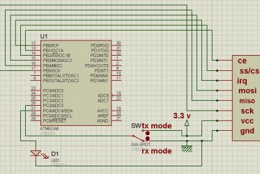
این تایپک رو گذاشتم تا استاد های محترم اشنایی کامل با راه اندازی این نوع ماژول در (BASCOM ) راه اندازی شده
با سلام
ماژول های بدون آنتن هم با برنامه ای که در پست اول گذاشتم
تست شد و کاملا جواب دادشماتیک پیوست گردید
من
دوتا ماژول بدون آنتن رو برای فاصله تست کردم
بیشتر از 100 متر جواب داد. البته جا نداشتم و به انتهای سالن رسیده بودم وگرنه فاصله رو بیشتر هم میکردم و مطمئنا جواب میداد.
در ضمن من
ترکیبی هم کار کردم جواب داد. مثلا فرستنده از ماژولای آنتن دار بود و گیرنده بدون آنتن و بالعکس و برنامه به خوبی جواب داد
فقط یک نکته اونم این که ممکنه پایه هارو چپرو بزنید و ماژول کار نکنه. من خودم در ابتدا همین اشتباه رو کردم. تصویر زیر به خوبی بیان گر پایه های ماژول هست. این تصویر توی اینترنت بود فقط من یکم دستکاریش کردم تا اشتباه برنگیز نباشه
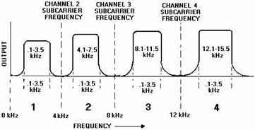
ب دیدیم که معمولا یک پهنای باند رو میان به چند زیر باند تقسیم میکنن
مثلا پهنای باند 2.3 گیگ تا 2.5 گیگ میشه 0.2 گیگ (200 مگا هرتز)
و اگه پهنای باند سیگنال مدوله شده 2 مگ باشه
200 تقسیم بر 2 میشه 100، یعنی 100 تا کانال مجزا داریم!
حالا برای دسترسی به این 100 کانال یا از شیوه ی آنالوگ استفاده میشه
یا از شیوه ی دیجیتال!
در اینجا (این ماژول) قابل برنامه ریزیه!
و پهنای باند سیگنال بستگی به سرعت ارسال داده ها،کمتر از 1 مگ، 1 مگ و 2 مگه.
خب.
در همون دیتاشیت در صفحه ی 15 جدول 6 هم اطلاعات خوبی داره.
صفحه ی 25 قسمت 6.3 رو هم یک نگاهی بندازیم:
The RF channel frequency is set by the RF_CH register according to the following formula:
F0= 2400 + RF_CH [MHz]
صفحه 58 قسمت RF Channel رو نگاه کنید: از 7 بیت برای انتخاب کانال میشه استفاده کرد
2 به توان 7 میشه 128 یعنی 128 کانال مختلف قابل تنظیمه!
یعنی ما میتونیم حدود (چرا حدود؟) 128 جفت ماژول مختلف رو با هم هم زمان راه اندازی کنیم
طوری که در کار هم تداخل نداشته باشن!

برای اطلاعات بیشتر تاپیک زیر رو مطالعه نمایید:
http://www.eca.ir/forum2/index.php?topic=82194
به صورت سوال جوابه بیشتر. حدود 8 صفحه ...
IRQ:
ماژول توسط این پایه به میکرو وقفه میدهد(در حالت عادی پایه high است و low شدن IRQ یکی از این حالت ها را می رساند:
1- در گیرنده یک پکت دریافت شده 2 - در فرستنده پکت بدرستی ارسال شده و ACK (تصدیق) دریافت شد 3- در فرستنده یک پکت چندبار ارسال شده(retransmition) ولی تصدیقی دریافت نکرده پس عمل فرستادن اطلاعات به درستی انجام نشده.
CE:
در حالت عادی low است وقتی بخواهیم اطلاعات با ماژول بفرستیم یا دریافت کنیم باید این پین را high کنیم تا ماژول از مد استندبای1 به active tx یا active rx برود(میتونید این پین را به VCC وصل کنید تا همیشه در حالت high باشد. ولی با وجود هدر شما فقط به PORTB.3 که وصل کنید به درستی عمل میکند(در define های اول هدر ذکر شده))
CSN:
در ارتباط spi به منظور پین CS یا ss استفاده میشود . در حالت عادی باید 1 باشد و وقتی با spi می خواهیم چیزی به ماژول بفرستیم باید آن را 0 کنیم
پروژه AVR راه اندازی ماژول NRF24L01 با کدویژن
به نام خدا
پروژه AVR راه اندازی ماژول NRF24L01 با کدویژن : تو این پروژه AVR من ماژول NRF24L01 رو راه اندازی کردم و پروژش رو براتون قرار دادم.

انواع ماژول NRF
این ماژول در 2 نوع آنتن دار و بدون آنتن وجود داه که نوع بدون آنتن (حدودا) بردش 100 متر و نوع آنتن دار 1100 متر هستش.

چیپ +NRF24L01 نمونه تصحیح شده با امکانات بیشتر و دیتا ریت بالاتر چیپ NRF2401 است که توسط شرکت NORDIC در اوایل سال 2008 معرفی شد.
این چیپ یک ماژول بسیار عالی برای ارسال و دریافت اطلاعات بدون خطا است چیزی که در ماژول های HMTR یا حتی در RFMXX ها یا به کلی وجود نداشت یا این که مشکلات خاص خود را داشت.
مدولاسیون ارتباطی این ماژول به صورت GFSK است , همان مدولاسیونی که در تکنولوژی BLUETOOTH استفاده شده و به صورت انحصاری در دست چند شرکت بزرگ مثل BLUETOOTH و NORDIC SEMICONDUCTOR و TEXAS INSTRUMENT و چند شرکت دیگر قرار دارد.
فرکانس ارتباطی این چیپ 2.4 گیگا هرتز است که این خاصیت آن ویژگی های زیادی را برای ما به ارمغان می آورد ! از جمله کوچک شدن سایز آنتن که حتی میتوان از خود PCB به صورت یک آنتن استفاده کرد , مورد دیگر هم به دلیل فرکانس بالا بسیار راحت تر از دیوار یا اجسام دیگر عبور می کند و با عث می شود که برد بیشتری هم به ما بدهد , می توانید فرکانس RFM12 یا HMTR را با این چیپ مقایسه کنید ! می بینید که فرکانس این سری از ماژول ها حداقل چند برابر آن ها است.
این چیپ به صورت دو طرفه کار می کند و در کل شما فقط به 2 عدد از این چیپ ها برای ارتباط لازم دارید (مشابه RDM12)
دیتا ریت این چیپ حداکثر 2 مگا بیت بر ثانیه است که می توان از آن برای انتقال اطلاعات سنگینی مشابه صوت و یا حتی ویدئو استفاده کرد.
توضیحات ماژول + NRF24L01 سری آنتن دار
ویژگی های خاص :
- طبقه تقویت کننده گیرنده و فرستنده داخلی
- چیپ با کیفیت تایوانی (ver 3.1)
- حداکثر دیتا ریت تا 2 مگا بیت بر ثانیه در فضای باز
- جریان مصرفی بسیار پایین (12 میلی آمپر)
- دارای رگولاتور داخلی و بی نیاز از تأمین ولتاژ های مختلف
- مجهز به تکنولوژِی پیشرفته SHOCKBURST
- قابلیت اتصال چند ماژول به هم از طریق بی سیم و ایجاد یک شبکه محلی
- قابلیت تحمل ولتاژ 5 ولت بر روی پین های دیتا
- سایز کوچک چیپ و نیاز به قطعات خارجی کم
توضیحات ماژول + NRF24L01 سری بدون آنتن
ویژگی های خاص:
- حداکثر دیتا ریت تا 2 مگا بیت بر ثانیه در فضای باز
- جریان مصرفی بسیار پایین (12 میلی آمپر)
- دارای رگولاتور داخلی و بی نیاز از تأمین ولتاژ های مختلف
- محدوده ولتاژ تغذیه چیپ از 1.9 تا 3.6 ولت
- مجهز به تکنولوژِی پیشرفته SHOCKBURST
- قابلیت اتصال چند ماژول به هم از طریق بی سیم و ایجاد یک شبکه محلی
- قابلیت تحمل ولتاژ 5 ولت بر روی پین های دیتا
- سایز کوچک چیپ و نیاز به قطعات خارجی کم
موارد استفاده:
- قطعات کامپیوتری وایرلس مانند موس یا کی بورد یا قطعات دیگر
- هدست های بیسیم مانند VOIP HEADSET
- دسته های بیسیم کنسول های بازی مانند PS3
- ساعت های ورزشی یا سنسور ها
- ریموت کنترل برای مصارف الکترونیکی
- اتوماسیون خانگی(خانه هوشمند) که فرضا تمامی ارتباطات الکتریکی فرضا برای روشنایی به صورت بیسیم می باشد
- در شبکه هایی که نیاز به یک ارتباط وایرلس بسیار کم مصرف است
- سیستم های مسیر یاب مانند GPS
- اسباب بازی ها !
- و در بسیاری از پروژه های متنوع صنعتی و غیرصنعتی که نیاز به یک ارتباط بی سیم مطمئن می باشد.
پروژه AVR
این از مدار ماژول گیرنده

این از کد های ماژول گیرنده
1
2
3
4
5
6
7
8
9
10
11
12
13
14
15
16
17
18
19
20
21
22
23
24
25
26
27
28
29
30
31
32
33
34
35
36
|
#include <mega32.h>
#include <nRF24L01+.h>
#include <stdio.h>
#include <delay.h>
#include <lcd.h>
#asm
.equ __lcd_port=0x1b
#endasm
char data1,str[33];
void main(void)
{
lcd_init(16);
nRF_Config(1);
lcd_puts("test1");delay_ms(1000);lcd_clear();
while (1)
{
if(State == 1)
{
data1 = payload[1];
lcd_gotoxy(0,1);
lcd_puts(" ");
sprintf(str,"Data = %d",data1);
lcd_gotoxy(0,1);
lcd_puts(str);
State = 0;
}
}
}
|
این از مدار ماژول فرستنده

اینم از کد های ماژول فرستنده
1
2
3
4
5
6
7
8
9
10
11
12
13
14
15
16
17
18
19
20
21
22
|
#include <mega32.h>
#include <stdio.h>
#include <delay.h>
#include <nRF24L01+.h>
char data1;
void main(void)
{
DDRA=0X00;
nRF_Config(0);
while (1)
{
while(PINA==0X01)
{
data1++;
Send_Data(1 , &data1);
}
}
}
|
ترتیب پایه های ماژول NRF
در زیر ترتیب پایه های برای ماژول NRF در دو نوع آنتن دار و بدون آنتن مشاهده میکنید که مثل هم هستن.


عکس پروژه + فیلم پروژه
فعلا درگیر کار های PCB ایش هستم…..(دنبال وسایل مورد نیاز!!!!) و منتظرم تا pcb ایش رو درست کنم و مدار رو روش ببندم و بعد فیلم بگیرم…..مدار رو من عملی بستم و جواب هم داده….لذا از این بابت نگران نباشید.
دانلود پروژه+دیتاشیت+بقیه مخلفات
دانلود آموزش فارسی راه اندازی ماژول وایرلس NRF24L01
+کدهای گیرنده و فرستنده+کتابخانه+پاورپوینت توضیحات و شماتیک
در قالب یک پروژه کاملا عملی

 nRF24L01 Demo code for Arduino (unknown, 4,705 hits)


 by
by 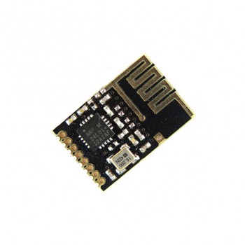









Thanks for this excellent write-up! I can’t wait to get home to try it. The Arduino IDE is great in general, but it’s leaps and bounds behind a fully fledged IDE like Eclipse. The Arduino project should really consider migrating to a dedicated Eclipse plugin (I know, I know, Eclipse complicates things which hurts the you-don’t-need-to-be-a-programmer concept behind Arduino).
The newer avrdude has a Arduino configuration for Hardware Configuration option which you can choose instead of Atmel STK500 Version 1.x Firmware… this fixed the avrdude: stk500_getsync(): not in sync: resp=0×00 message for me.
[…] You can download a free and open source Arduino IDE from Arduino.cc. It works pretty well and includes lots of example sketches to learn about the Arduino. Once you are comfortable with the basics you can upgrade to using Eclipse as your main IDE for Arduino. […]
hi,
nice tutorial, compiles fine on ubuntu 9.10, … but I got a major problem …
Does anyone experience an expansion of the .hex file from about 2000 bytes to over 8000 bytes once the Serial.begin and Serial.println commands are added? By leaving out the includes and changing global includes in Tone.cpp to local ones I could get the basic size down to about 1300 bytes, but once the Serial commands were back in it exceeded the 8k. I would usually not care about that, but as there are only 14k available on my Diecimila and the almost empty project takes more than half of the memory its a problem. I compiled the same code in the Arduino IDE and it told me the generated file was about 2300 bytes … so whats goin on? Might it be that there is some other serial lib compiled in? Shouldn’t that be the same Wiring code in the core anyway?
cheers rob
Hi,
Your description of getting eclipse to play nicely with Arduino was pretty good. It helped me a lot.
A million thanks for this.
I’ve been trying various tutorials on how to do exactly this for a few weeks and this is the first time I managed to get it to compile. Thanks for taking the time to write it up.
I’m mostly a beginner when it comes to both C programming and AVR. I like Eclipse however and have used it for Java for a while. Having said that, I met with a few errors while following your directions. I don’t know if they are my fault through ignorance or not, but I’ll describe them here anyway in case they might be of some use.
First error I got was with the linker command line pattern. I got a compiler error “avr-gcc.exe: –cref: No such file or directory”. It looks like the “–cref” should be “–cref”. After changing that I got a different error saying “ld.exe: cannot find -lArduinoCore”. Eventually, after trying just about everything I could think of I discovered that I needed both the name of the library in the “-l” box and the file location in the “-L” box. This might very well be a simple mistake, but it’s not clear to a novice.
After that it compiled perfectly and that’s as far as I’ve got for now. I don’t have my hardware with me as I’m writing this, so I can’t test the upload instructions.
Thanks again for posting this stuff, as I said I’m a big fan of Eclipse and being able to write AVR code with it makes life a lot easier.
I’m with DubiousTech on this one. Great article, but if you copy the command line arguments string from this website and paste them into your settings dialog box in Eclipse, things won’t compile. I spent a couple hours reinstalling everything and starting from scratch, because all my settings were copies of what is in this tutorial. I wish I had read the comments to this post and seen DubiousTech’s post … I would have saved a couple hours.
You’ve got to update this post so the dash in front of “cref” is actually two dashes. Please?
The programmer Atmel stk500v1 does not work with my arduino Duemilanove and it aways break the avr-dude and throw this message:
avrdude: stk500_recv(): programmer is not responding
avrdude done. Thank you.
Any suggestions?
[…] that’s another post. I wonder how much work a dedicated Arduino eclipse plugin would take. Using Eclipse with Arduino Duemilnove at Chipkin looks like the newest one. This one creates a C++ project, and says to set the baud rate […]
The comments all have one dash in front of cref. Perhaps there’s a CSS problem on this site? The source text may well have two dashes, leaving the author confused. It may even be browser-specific (I’m on Firefox on Windows).
Let’s try: One dash: “-cref” two dashes: “–cref”
Yep, I get a short dash and a long dash, but definitely just one character both times. The article definitely needs to be fixed, but it’s not simple to fix.
Caution: I had the same “avr-gcc.exe: –cref: No such file or directory” error and tried to add a dash in front of cref. This does not work! Since I’ve copied the command line from the tutorial I had one long dash, adding an extra dash results in having a long and a short dash which will throw an error. One has to delete the copied (long) dash and add two normal (short) dashes!
It’s obvious but believe me or not, it took me almost an hour to fix that :)
Thanks for the awesome tutorial!
Hi,
I got it nicely working. The only issue I have is that I have an issue with timings.
For example the delay statement below does note delay 5 and 5 seconds, it looks like it delays only about a 10th of it.
I checked that the F_CPU is set correctly to 1600000L wiht the -DF_CPU=16000000L command.
When I use the same source wiht in teh Arduino 0018 envirnment the delay is ok, Wiht Eclipse it is much shorter.
void loop()
{
digitalWrite(ledPin, HIGH); // set the LED on
delay(5000); // wait for a second
digitalWrite(ledPin, LOW); // set the LED off
delay(1000); // wait for a second
}
I’ve tried the tutorial, everything worked as planed. I didn’t had any timing/delay issues with Eclipse compared to the Arduino IDE. Did you use any other parameters? I didn’t specify -DF_CPU, nor any additional values… works like planed without that.
I really love what you post here, very insightful and intelligent. One thing though, I’m running Firefox on Linux and some of your layout pieces are a little off. I know it’s not a popular setup, but it’s still something to watch out for. Just shooting you a heads up.
great tutorial. But, I can not get eclipse to compile the Timer1 (http://www.arduino.cc/playground/Code/Timer1) library correctly when following these instructions. I managed to get the library to work with eclipse by first compiling the library with the Arduino IDE and including the object file in my eclipse project. More specifically, I created a simple sketch that included the Timer1 library, compiled the project, copied the TimerOne.cpp.o file from C:\Users\\AppData\Local\Temp\buildXXXXXXXXXXXXXXXXXXXXX.tmp\Timer1 into my eclipse project along with the the TimerOne.h file (excluded TimerOne.cpp), added “TimerOne.cpp.o” to the “Other Objects” panel within Project => Properties => C/C++ Build => Settings => AVR C++ Linker => Objects.
What settings are required so eclipse compiles this and similar libraries correctly? Currently, eclipse compiles the library, but the code does not operate appropriately. In my case, I’m using the timer library to control a step pin of a stepper motor driver. My stepper motor does not work when compiling the library with eclipse.
First of all, this is an excellent cook book.
However, it looks like that I am the only dummy to get things up and running.
– Installed all files according to “Download”, with the exception I got Arduino 0019.
– Followed your Build Library instruction: got 8 warnings: This file has moved to util\delay.h
– Followed your Create Project instruction (with the exception ArduinoCore is referenced to it’s release dir)
Getting the following errors:
Description Resource Path Location Type
make: *** [Test.elf] Error 1 Test C/C++ Problem
undefined reference to `main’ Test line 0 C/C++ Problem
make all
Building target: Test.elf
Invoking: AVR C++ Linker
avr-g++ -Wl,-Map,Test.map,–cref -mmcu=atmega328p -o”Test.elf” ./main.o
c:/program files/winavr/bin/../lib/gcc/avr/4.3.3/../../../../avr/lib/avr5/crtm328p.o:(.init9+0x0): undefined reference to `main’
make: *** [Test.elf] Error 1
I know that must be a simple setting which I cannot find, since I am new with Eclipse (which I like). Your help is much appreciated.
Dear All,
got it to work, at the third attempt it worked, ignore above.
R.
many thanks for the great tutorial. I am a beginner and would almost give up the Arduino to marry eclipse. My first project is working now. Now I want to debug using eclipse it. Is there even such a simple tutorial on this?
greet willi
google trans later thanks
I was getting the same error as Eduardo and was able to fix it by changing the baud rate to 19200. My Arduino is using the ATMEGA168.
So is there a way to create a default configuration so we don’t always have to go and set compiler, linker, and build options?
Firstly, thanks very much for this. The Arduino IDE drives me nuts and Eclipse is a breath of fresh air.
I appear to be having the same problem as Robby was. Although mine does not seem to go away by itself. I followed the steps exactly with the exception of the same step that Robby modified (pointing the IDE at the release folder for ArduinoCore). The following is what I get for an error.
Building target: Blinky.elf
Invoking: AVR C++ Linker
avr-gcc –cref -s -Os -o”Blinky.elf” ./Main.o -lArduinoCore -lm -Wl,-Map,Blinky.map,–cref -L”X:\ArduinoCore\Release” -mmcu=atmega328p
c:/winavr-20100110/bin/../lib/gcc/avr/4.3.3/../../../../avr/lib/avr5/crtm328p.o:(.init9+0x0): undefined reference to `main’
make: *** [Blinky.elf] Error 1
Any help would be appreciated…
Further to my previous post. I get the same error when I move the libArduinoCore.a to the project folder and adjust the library path accordingly.
One more bit of information… I did the same installation on my Linux machine (which where I prefer to work anyway) and I get pretty much the same error.
Building target: Blinky.elf
Invoking: AVR C++ Linker
avr-gcc –cref -s -Os -o”Blinky.elf” ./main.o -lArduinoCore -lm -Wl,-Map,Blinky.map,–cref -L/home/nwild/workspace/ArduinoCore/Release -mmcu=atmega328p
/usr/lib/gcc/avr/4.3.4/../../../avr/lib/avr5/crtm328p.o: In function `__bad_interrupt':
../../../../crt1/gcrt1.S:193: undefined reference to `main’
make: *** [Blinky.elf] Error 1
Obviously I am missing something?! Thanks for any help…
If anyone is following up on this using the latest version of Arduino, you may run into the following bug when trying
to build the Arduino core library:
In the file Tone.cpp (tone generator library), there will be multiple compile errors, because there’s apparently a small bug
in the code.
The following two includes are specified incorrectly:
#include
#include
they should instead read:
#include “wiring.h”
#include “pins_arduino.h”
Because these headers are LOCAL to the project, and not in the [WinAVR] include path!
(I have no idea how the whole thing compiles in the first place when using the Arduino IDE…)
Hope this helps :-)
Please, help me.
I’m with problem in use the command Serial.print. Follow bellow the command full:
int val = 10;
Serial.print(val,DEC);
———————-
The error is showed:
Building target: rastreador_new.elf
Invoking: AVR C++ Linker
avr-g++ -Wl,-Map,rastreador_new.map,–cref -L”/home/test/source/test” -mmcu=atmega168 -o”rastreador_new.elf” ./SoftwareSerial.o ./gps_api.o ./main.o ./template.o -lcore
./main.o: In function `loop':
main.cpp:(.text+0x28): undefined reference to `Print::print(int, int)’
I’m using linux ubuntu 9.10.
Thanks.
Hi,
I’ve got the following two problems and I hope that there is anybody out there who can help me:
1. I’m only able to flash my Arduino Duemilanove if I choose “Arduino” within the AVRDude settings. “STK500v1″ is not working. I got a no response error.
2. I’m unable to flash an Arduino UNO with AVRDude (WinAVR20101010). There are no settings within the AVDDude settings which are working. I got a no response error.
Thanks for your help.
Hint:
I solved the problems:
1. Arduino Duemilanove: AVRDude Programmer:”Arduino” and baudrate fixed to “115200” baud. 57600baud for example is n o t working.
2. Arduino UNO: AVRDude Programmer:”Arduino” and baudrate fixed to “115200” baud. 57600baud for example is n o t working.
Hello everybody
i am getting following error.
it says avr-gcc.exe: lm: No such file or directory
but i am unable to fix this problem. can anybody help me. thanking you
with regards
pasa
**** Build of configuration Release for project atmegaproject ****
make all
Building file: ../main.cpp
Invoking: AVR C++ Compiler
avr-gcc -I”D:\arduino\arduino-0021\hardware\arduino\cores\arduino” -Wall -Os -fpack-struct -fshort-enums -funsigned-char -funsigned-bitfields -fno-exceptions -mmcu=atmega328p -DF_CPU=16000000UL -MMD -MP -MF”main.d” -MT”main.d” -c -o”main.o” “../main.cpp”
Finished building: ../main.cpp
Building target: atmegaproject.elf
Invoking: AVR C++ Linker
avr-gcc –cref -s -Os -o”atmegaproject.elf” ./main.o -lArduinoCore – lm -Wl,-Map,atmegaproject.map,–cref -L”C:\Users\psilpakar\Contacts\workspace\ArduinoCore\Release” -mmcu=atmega328p
avr-gcc.exe: lm: No such file or directory
avr-gcc.exe: -E or -x required when input is from standard input
make: *** [atmegaproject.elf] Error 1
Thanks so much for this. I’ve spent the entire day going over other tutorials with no success. Yours was the first that worked.
A great tutorial and it works :)
@pasapasa
There should be no space between “- lm”.
Thank you so much!! I have Arduino Uno, I tried for a long time to use Eclipse, and now, using your project “Blinky” it works!!!!
To make AVRDUDE work, I substituite the versione “avrdude.exe” gived in WINAVR with the one gived in Arduino-0021 IDE.
Please help!
I have followed this tutorial but I can not compile the project.
I am using eclipse helios for 64 bits and I have done the set up as in the tutorial but I get the error:
Invoking: AVR C++ Linker
avr-gcc –cref -s -Os -o”ArduinoCore.elf” ./main.o -llibArduinoCore -lm -Wl,-Map,ArduinoCore.map,–cref -L”D:\EclipseWorkSpace\ArduinoCore” -mmcu=atmega1281
c:/winavr-20100110/bin/../lib/gcc/avr/4.3.3/../../../../avr/bin/ld.exe: cannot find -llibArduinoCore
However, the path of libArduidoCore.a is well specified in the AVR C++ Linker.
Thanks for the tutotial.
hi.
great article that got me up and running quite quickly.
I have a question…
is there a way to make all of the configuration process into some kind of template
so that you can choose it when creating a new project?
I mean…
I’d love to be able and just select a new project of that type without having to re-set all the paths,
library, configuration options
looking forward to an answer
ciao.ubi
I really like the Eclipse environment but I am not familiar with it at all. I created the Blinky project and encountered the following error that I can’t seem to get rid of. Please help.
Building target: Blinky.elf
Invoking: AVR C++ Linker
avr-gcc –cref -s -Os -o”Blinky.elf” ./main.o -lArduinoCore -lm -Wl,-Map,Blinky.map,–cref -L”C:\Users\Marius\Arduino\ArduinoCore” -mmcu=atmega328
c:/users/marius/my programs/winavr/bin/../lib/gcc/avr/4.3.3/../../../../avr/lib/avr5/crtm328.o:(.init9+0x0): undefined reference to `main’
make: *** [Blinky.elf] Error 1
Okey! I spend a very long time before programming success, so I hope this can help some people:
I have an Arduino UNO with Arduino-0022 IDE.
My command line is:
C:\WinAVR-20100110\bin\avrdude -pm328p -cstk500v1 -P//./COM11 -b115200 -F -Uflash:w:Blinky.hex:a
Thanks for this tutorial and enjoy;)
Josino,
i think your problem in this command:
avr-gcc –cref -s -Os -o”ArduinoCore.elf” ./main.o -llibArduinoCore
-lm -Wl,-Map,ArduinoCore.map,–cref
-L”D:\EclipseWorkSpace\ArduinoCore” -mmcu=atmega1281
is “-llibArduinoCore”:
You should have used just the name of the library, without the “lib” prefix.
Great Man. Got it work on x64 eclipse!
Great tutorial but i have some problems. I want to use the Ethernet.h.
I copied the Ethernet and SPI directory from arduino022/libraries to my project.
Then i changed the paths in order to be correct but i doesn’t work.
I get these errors
Building target: Blinky.elf
Invoking: AVR C++ Linker
avr-g++ -Wl,-Map,Blinky.map,–cref -L”C:\Users\plush\Desktop\projects\Blinky” -mmcu=atmega328p -o “Blinky.elf” ./main.o ./SPI/SPI.o ./Ethernet/utility/socket.o ./Ethernet/utility/w5100.o ./Ethernet/Client.o ./Ethernet/Ethernet.o ./Ethernet/Server.o ./Ethernet/Udp.o -lArduinoCore
./Ethernet/Client.o:(.data+0x18): undefined reference to `__cxa_pure_virtual’
./Ethernet/Client.o:(.data+0x1e): undefined reference to `__cxa_pure_virtual’
./Ethernet/Client.o:(.data+0x20): undefined reference to `__cxa_pure_virtual’
./Ethernet/Client.o:(.data+0x22): undefined reference to `__cxa_pure_virtual’
./Ethernet/Client.o:(.data+0x24): undefined reference to `__cxa_pure_virtual’
./Ethernet/Server.o:(.data+0xe): more undefined references to `__cxa_pure_virtual’ follow
make: *** [Blinky.elf] Error 1
Am i doing this correctly? Please help.
Hello
great tutorial , but i have one problem
I skiped step “Build the Arduino library”, and i made step by step step “Creating a Arduino project”, but after click on Project =>Build All, there is error
“Description Resource Path Location Type
make: *** [main.o] Error 258 Blinky line 0 C/C++ Problem
“, i have same versions as written in “Setting up the Eclipse environment”
Do somebody know where is the problem?
here is console outpu
**** Build of configuration Release for project Blinky ****
make all
Building file: ../main.cpp
Invoking: AVR C++ Compiler
avr-g++ -I”h:\prg\_microcontrolers\arduino-0018\hardware\arduino\cores\arduino\” -Wall -Os -fpack-struct -fshort-enums -mmcu=atmega1280 -DF_CPU=16000000UL -MMD -MP -MF”main.d” -MT”main.d” -c -o”main.o” “../main.cpp”
/usr/bin/sh: -c: line 1: unexpected EOF while looking for matching `”‘
/usr/bin/sh: -c: line 2: syntax error: unexpected end of file
make: *** [main.o] Error 258
Hi there,
I always new that Eclipse was a poor software – to put it politely – but going through what you people do …
I was to try it, maybe it become better during the last 4 years I didn’t touch it but … it was throwing errors galore during install.
They can’t even create a proper install-instruction page! One has to hunt for the solution for hours.
And now, the instructions above are faulty, there is no directory in the eclipse-avr-plugin as the instruction says …
I’m SICK of this. Nobody can make or do anything properly any more! Forget about this whole lot, stick to my trusty c++ text editor.
And you guys just struggle with Eclipse and the lot.
Cheers!
Excellent write up. I was able to set up Eclipse with AVR using these instructions. Off course only one compile error related to make file, needed –cref, that fixed it. However the AVRdude uploads file to my UNO board, but I get no blinks at all and idea that how can I debug this. I have tried baud rate 57600, but no luck, so I using 115200. At pointers or hints?
I’ve tried several howto’s to get Eclipse running with Arduino, this guide was spot on and it worked first time! Well written. :)
To all of you guys who experience time problems with the Blink project. When you change the sleep interval you must build again (Ctrl+B) before deploying to the Arduino.
[…] is a combination of the following sources: Arduino mit Eclipse als IDE (sorry, german only) Using Eclipse with Arduino Duemilanove AVR-Programmierung am Mac mit Eclipse: make-Problem (german again) Veröffentlich unter […]
Thank Your for this great tutorial!
But i cant build the example.
I got the following error:
[c]
Building target: ArduinoCore.elf
Invoking: AVR C++ Linker
avr-gcc –cref -s -Os -o”ArduinoCore.elf” ./HardwareSerial.o ./Print.o ./Tone.o ./WInterrupts.o ./WMath.o ./pins_arduino.o ./wiring.o ./wiring_analog.o ./wiring_digital.o ./wiring_pulse.o ./wiring_shift.o -lArduinoCore -lm -Wl,-Map,ArduinoCore.map,–cref -L”C:\Documents and Settings\Administrator\workspace\ArduinoCore” -mmcu=atmega328p
c:/documents and settings/administrator/desktop/arduino-0018/hardware/tools/avr/bin/../lib/gcc/avr/4.3.2/../../../../avr/lib/avr5/crtm328p.o:(.init9+0x0): undefined reference to `main’
make: *** [ArduinoCore.elf] Error 1
**** Build Finished ****
[/c]
Cheers!
There is now a eclipse plugin that works with the avrdude and compiler delivered with Arduino IDE.
This makes the installation process a lot easier.
Read more at http://eclipse.baeyens.it
Best regards
Jante
[…] followed this tutorial by Steven Smethurst and using this page to install the Arduino plugin, that got me to the point where I can build the […]
Hi
My board is Andruino Uno R3 and I am getting following error:
avrdude: stk500_getsync(): not in sync: resp=0x00
avrdude done. Thank you.
I try everything: disconnect and reconnect, changes in connect options etc. Any ideas??
Thanks for this tutorial. I got it all working, except…
The LED does not blink!
Building libraries, main.cpp, uploading to Arduino, no problem at all, no warnings, no errors, but whatever I try, after uploading the LED does not blink!
Thanks for this tutorial. I experienced one particularly nasty error when building the Blink project; ld.exe crashed hard with a win32 exception (on Windows 7 32 bit, using Arduino 1.0.5 but I also tried with 1.0.2 and had the same problem). Removing the relax flag from the build settings helped. I don’t know whether this is the default setting as I downloaded the project somewhere from Github. Anyway, here goes the info for the records.
Thanks for the tutorial!
All goes well till the linking part.
Building target: TestAVR.elf
Invoking: AVR C++ Linker
avr-gcc –cref -s -Os -o”TestAVR.elf” ./src/main.o -lArduinoCore -lm -Wl,-Map,TestAVR.map,–cref -mrelax -Wl,–gc-sections -L/home/harsh/workspace/avr/ArduinoCore/Release -mmcu=atmega328p
collect2: ld terminated with signal 11 [Segmentation fault], core dumped
make: *** [TestAVR.elf] Error 1
Binutils is the latest version