برق، الکترونیک، الکتروتکنیک، مکاترونیک، پزشکی، کشاورزی

برق، الکترونیک، الکتروتکنیک، مکاترونیک، پزشکی، کشاورزی و

برق، الکترونیک، الکتروتکنیک، مکاترونیک، پزشکی، کشاورزی

برق، الکترونیک، الکتروتکنیک، مکاترونیک، پزشکی، کشاورزی و

داده هایی در مورد برق، الکترونیک، الکتروتکنیک، مکاترونیک، پزشکی، کشاورزی و

تبلیغات
آخرین نظرات

۱۰ مطلب با کلمه‌ی کلیدی «دوربین های صنعتی فریم بالا» ثبت شده است

دوربین های صنعتی فریم بالا 8

ShahBaz | پنجشنبه, ۱۹ آذر ۱۳۹۴، ۱۰:۵۲ ب.ظ

QImaging Scientific Cameras

Retiga R1™ CCD Camera


Retiga R1 Camera

Telling the story behind great science… at a happily ever after price.

The Retiga R1 has the technical features you need in a scientific camera to improve limits of detection and quantification. More importantly, the camera becomes an intuitive extension of your imaging system, smoothly delivering data from the super speed USB3.0 interface to your computer.

Inside the R1 camera, QImaging introduces Intelligent Quantification™ - on camera intelligence features that correct for defective pixels, remove accumulated dark current, and make high dynamic range imaging available. Fast 50 MHz pixel digitization increases camera frame rate to give you all the speed you need for any laboratory imaging challenge.

A great camera deserves great software for acquisition. Ocular™ is QImaging's all new imaging platform that's included in every camera purchase and ready to become your go-to capture program. View the Ocular video!

Features

  • 75% peak QE combined with low noise electronics reveals the weak signals missed by industrial cameras
  • Increased exposure time and binning enables detection of the faintest signals with deep sensor cooling
  • 50MHz two port readout delivers frame rate for finding, focusing and imaging samples
  • Reduce photobleaching and phototoxicity on samples.
  • Intelligent Quantification™ provides advanced real-time FPGA algorithms to deliver better image quality
  • New Ocular™ imaging software


pco.edge 4.2 scientific imaging camera achieves 100 fps

pco.edge 4.2 MPixel camera

PCO’s pco.edge 4.2 MPixel camera features a scientific CMOS image sensor with 6.5 µm x 6.5 µm pixel size, rolling shutter, and 70% quantum efficiency. The pco.edge 4.2 achieves a frame rate of 100 fps at 2,048 x 2,048 pixels on fast scan mode and is available with a Camera Link or USB 3.0 interface. In addition, the cameras feature temperature-stabilized Peltier cooling, which allows for continuous operation free of drift phenomena in image sequences capture. These cameras are suitable for use in life and physical sciences, industrial research, machine vision, and hyperspectral imaging applications.

To Learn More:

Contact: PCO
Headquarters
: Kelheim, Germany
Product: 
pco.edge 4.2 MPixel camera
Key Features:
  scientific CMOS image sensor with 6.5 µm x 6.5 µm pixel size, rolling shutter, 70% quantum efficiency, Camera Link or USB 3.0 interface.

What PCO says:
View more information on the pco.edge 4.2 camera.

View More ProductsLocate a vendor or system integrator | Receive e-mail updates

Share new products that you think are particularly interesting or helpful by contacting James Carroll, Senior Web Editor, Vision Systems Design.


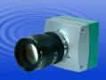
Mikrotron MC1302, MC1303
High Speed Digital Cameras

High Speed, 100fps MegaPixel
CMOS Camera


Camera Kits  
Mikrotron High Speed Cameras
Click here to visit
Mikrotron Web Site
Camera Link

  • MC1302 monochrome
  • MC1303 RGB colour with BAYER filter
  • Up to 100 fps @ 1280 (H) x 1024 (V) resolution
  • 1024 or 256 grey scales
  • Camera Link™ output with 660 Mbyte/s max. data rate
  • Random selection of window size and position  Asynchronous global shutter
  • Horizontal und vertical pixel binning
  • ImageBLITZimage trigger
  • Low power consumption
  • Small, compact size

MotionBLITZ Kit Now Available
Includes Camera, Frame Grabber, Cable, Software etc

 Other High Speed Cameras from Mikrotron

 Features
 Specifications

  Product Specifications

Ask us About the MC1302/MC1303 ?

Need a lens ? Need a lens ?
Std C/CS mount macro,
vari-focal & zoom lenses.
Camera Link Cables 
Compatible Frame Grabbers
 (Camera Interfacing)
 
Features

 
Flexible resolution and speed

Mikrotrons MC1302/03 are high-speed megaPixel CMOS cameras with a resolution of 1280 (H) x 1024 (V) pixel. In contrast to high resolution CCD-imagers, modern CMOS-sensors offer high resolution and extremely high data rates. Because window size, position (ROI), and clock frequency is randomly program-mable, resolution and frame rate of MC1302/03 can be easily adapted to any specific requirements.

Easy configuration
MC1302/03 configuration is done via the Camera Link ™ interface. Eight sets of camera configuration schemes can be stored in non-volatile memory of the cameras microcontroller. Even the FPGA configuration file can be downloaded for very special customer needs e.g.: image preprocessing in MC1302/03 hardware.

Window size and position (ROI) on the imager plus clock speed are programmable. With a pixel clock of 33 MHz on the "Base" Camera Link™ connector and a window size of 100 x 100 pixel a frame rate of more than 4.850 fps can be achieved. Maximum video data rate at the 64-bit "Full" Camera Link™ connector is 660 Mbyte/sec.

"Freeze Frame" full frame shutter
The MC1302/03 has a "Freeze Frame" shutter. This shutter "freezes" and stores the complete full frame at the end of the exposure time while exposing the next image.

In this way the full frame shutter makes the sharply defined ex-posure of very fast, dynamic processes possible.

MC1302/03 can expose images synchronously or asynchronously. In synchronous (free run) mode exposure time equals frame time or, for shorter exposure times, the electronic shutter can be activated with a minimal shutter time of 4µs. In asynchro-nous mode an image is exposed by an external trigger.

Camera Link™ compatible output
Using 2x10-Bit data output the full dynamic range of the sensor is available on the output. If less bandwidth and more speed is desired, any 8-Bits out of the 10-Bits of the sensor can be selected and output as 2x8-Bit or 8x8-Bit as full Camera Link™ output format.

Horizontal and Vertical Pixelbinning
With high frame rates the exposure time is short. For more sensitivity the grey level of two adjacent or pixel in one row or one column or both can be summed.

ImageBLITZ.Image trigger
ImageBLITZ. integrates the function of an optical sensor or any other external actuator inside MC1302/03 hardware without any support of an image processing system.

The hardware inside the camera controls with very high repetition rate the intensity along an arbitrary selectable piece of one of the 1024 rows of the imager. If along that piece of the selected row a selectable number of grey values are beyond or below a selectable threshold, one complete image is automatically exposed and output.

This is the advantage: no mounting and adjustment of an optical sensor and each object is captured at the exact same position of the image.

Camera configuration tool
The MC1302/03 is delivered with a configuration program for Windows™ operating systems. The clearly defined control surface allows to work with it intuitively. All parameters of the camera may be set directly or via sliders. The resulting commands are transmitted by the serial interface of Camera Link™ and can be reviewed by the integrated command monitor. The selected settings may be stored in the camera or in a separate file


Mikrotron MotionBLITZ Kits
    

MotionBLITZ Kits include the following
components:
- High speed monochrome/colour camera 
- High Speed Interface Card
- Camera Link Cables
- Power supply
- Optocoupled Digital Input/output cable 
- Standard C-mount, optional F-mount
- MotionBLITZ Director Software


Specifications

Specifications
Mikrotron's MC1302/1303 camera series are equipped with a digital video interface that conforms to the Camera Link industry standard. These cameras enable the capture of high-speed, high-resolution images while simplifying connectivity to machine-vision systems with its standard 3M MDR 26-pin cable.
 

MC1302 Sensor
MC1303 Sensor

Linear response, monochrome
RGB colour with BAYER filter and UV-IR filter

Number of Pixels 1280(H) x 1024(V)
Optical Active Area 12 x 12 µm(H/V)
Fill Factor 40%
Spectral Bandwidth 400-800nm
Illumination @ ADC Vref=1V 1600 LSBlux/sec at 550nm
Dynamics 59 dB
Frame Rate 100fps @ 1280 x1024 Pixels
1000 fps @1280 x 360 Pixels
4956 fps @1280 x 100 Pixels
Video Output "Base" Camera Link 
2 x 8-bit or 2 x 10-bit
Synchronisation Internal or External
Pixel Clock 7.5 - 85MHz
Asynchronous Shutter Internal Timer, 1024 steps, 4us to 32ms or by pulse width trigger signal
Gain Digital x 1, 2, 4
Camera Configuration "Base" Camera Link
Power Supply 8 - 35V DC

Power consumption max.
100*100 @ 4956fps typ.
1280*1024 @ 47fps typ.
Thermal resistance typ.

6.5W
4.9W
2.4W
0.17°/W

Case Temperature 5 to 50 °C
Size 63 x 63 x 47 mm
Weight ~ 300g
Lens C-Mount, F-Mount with adapter

Ordering Information

Cameras

MC1302

Monochrome, 1280x1024 Pixels, 100fps, Camera Link, C-Mount

MC1308

Monochrome, 1280x1024 Pixels, 100fps, Camera Link, F-Mount

MC1303

Colour, 1280x1024 Pixels, 100fps, Camera Link, C-Mount

MC1309

Colour, 1280x1024 Pixels, 100fps, Camera Link, F-Mount

Accessories

Camera Cables

KKRDCLSR-03

26pin CameraLink Cable, 3m

KKRDCLSR-05

26pin CameraLink Cable, 5m

KKRDCLSR-10

26pin CameraLink Cable, 10m

Power Cables

KKRPMC13XX-03

Mikrotron Power cable for MC13XX - 3m

KKRPMC13XX-05

Mikrotron Power cable for MC13XX - 5m

KKRPMC13XX-10

Mikrotron Power cable for MC13XX - 10m


MotionBLITZ Kits
High Speed Camera System with variable frame rate and resolution

CAMMB-KIT-1M1

MotionBLITZ®-Kit 1M1 High Speed Camera System with variable frame rate and resolution, up to 16,000 fps and up to 8 sec. recording time, monochrome, 100fps @ 1280(H)*1024(V)
CAMMB-KIT-1C1 MotionBLITZ®-Kit 1C1 High Speed Camera System with variable frame rate and resolution, up to16,000 fps and up to 8 sec. recording time, colour, 100fps @ 1280(H)*1024(V)
CAMMB-KIT-1M MotionBLITZ®-Kit 1M  High Speed Camera System with variable frame rate and resolution, up to 16,000 fps and up to 1.5 sec. recording time, monochrome, 500fps @ 1280(H)*1024(V)
CAMMB-KIT-1C MotionBLITZ®-Kit 1C High Speed Camera System with variable frame rate and resolution, up to 16,000 fps and up to 1.5 sec. recording time, colour, 500fps @ 1280(H)*1024(V)
Consist of the following components
  - Camera with MegaPixel sensor, resolution 1280(H)*1024(V)
  - Monochrome or colour
  - 100 / 500 full fps, adjustable up to 16.000 fps at reduced resolution
  - PCI/PCI-X camera control and frame store board with 1GB onboard memory
  - 1 / 2x Camera Link® cable, 5m
  - Camera power supply
  - Rear panel cable (KMFK1003 / KMFK1010) for external trigger and PC-bracket
  - C-mount, F-mount with adapter (optional)
  - MotionBLITZ® installations- and usersoftware for Windows 2000/XP™
Mikrotron MotionBLITZ® Director features
  - Camera control
  - Resolution/Region of Interest (ROI)
  - Speed (frames per second, fps)
  - shutter time
  - Recording control
  - Single/multi-sequence
  - Play-back of recorded sequences
  - Select and edit sequences as
  - Video in .avi-format
  - Single or multiple images as .bmp-files
  - Offline version for desktop offline use available


  • ShahBaz

دوربین های صنعتی فریم بالا 6

ShahBaz | پنجشنبه, ۱۹ آذر ۱۳۹۴، ۱۰:۳۴ ب.ظ

http://www.theimagingsource.com/en_US/products/cameras/usb-cmos-ccd-color/

اگر قصد خرید دوربین با فریم بالا دارید لطفا با ایمیل eshahnazi@gmail.com در ارتباط باشید. و یا با شماره 09138988351 تماس بگیرید.
تلگرام: https://telegram.me/shah_baz


DFK 23UP1300

The Imaging Source DFK 23UP1300
Lens not included
  • USB 3.0 Color Industrial Camera
  • 1/2 " OnSemi Python
  • 1280x1024 pixel
  • Trigger input and I/O
  • WindowsWindows and LinuxLinux software included
Get Quotation - DFK 23UP1300
Tel: +49 (0)421 335 91 0
Subject to change
GENERAL BEHAVIOR
Video formats @ Frame rate 1280x1024 Y800 @ 95, 90, 85, 80, 75, 70, 65, 60, 55, 50, 45, 40, 35, 30, 25, 20, 15, 10, 5 fps
1280x1024 Y16 @ 45, 40, 35, 30, 25, 20, 15, 10, 5 fps
1280x1024 RGB32 @ 95, 90, 85, 80, 75, 70, 65, 60, 55, 50, 45, 40, 35, 30, 25, 20, 15, 10, 5 fps
Dynamic range 8 / 12 bit
INTERFACE (OPTICAL)
IR cut filter yes
Sensor specification  ON Semiconductor PYTHON 1300 [PDF]
Shutter Global
Format 1/2 "
Resolution H: 1280, V: 1024
Pixel size H: 4.8 µm, V: 4.8 µm
Lens mount C/CS
INTERFACE (ELECTRICAL)
Interface USB 3.0
Supply voltage 4.5 to 5.5 VDC
Current consumption approx 250 mA at 5 VDC
INTERFACE (MECHANICAL)
Dimensions H: 29 mm, W: 29 mm, L: 43 mm
Mass 65 g
ADJUSTMENTS (MAN)
Shutter 1/100000 to 30 s
Gain 0 to 36 dB
White balance -2 dB to +6 dB
ADJUSTMENTS (AUTO)
Shutter 1/100000 to 30 s
Gain 0 to 36 dB
White balance -2 dB to +6 dB
ENVIRONMENTAL
Max. temperature (operation) -5 °C to 45 °C
Max. temperature (storage) -20 °C to 60 °C
Max. humidity (operation) 20 % to 80 % non-condensing
Max. humidity (storage) 20 % to 95 % non-condensing


اگر قصد خرید دوربین با فریم بالا دارید لطفا با ایمیل eshahnazi@gmail.com در ارتباط باشید. و یا با شماره 09138988351 تماس بگیرید.
تلگرام: https://telegram.me/shah_baz

DFK 23UP1300

The Imaging Source DFK 23UP1300
Lens not included
  • USB 3.0 Color Industrial Camera
  • 1/2 " OnSemi Python
  • 1280x1024 pixel
  • Trigger input and I/O
  • WindowsWindows and LinuxLinux software included
Get Quotation - DFK 23UP1300
Tel: +49 (0)421 335 91 0
Subject to change
GENERAL BEHAVIOR
Video formats @ Frame rate 1280x1024 Y800 @ 95, 90, 85, 80, 75, 70, 65, 60, 55, 50, 45, 40, 35, 30, 25, 20, 15, 10, 5 fps
1280x1024 Y16 @ 45, 40, 35, 30, 25, 20, 15, 10, 5 fps
1280x1024 RGB32 @ 95, 90, 85, 80, 75, 70, 65, 60, 55, 50, 45, 40, 35, 30, 25, 20, 15, 10, 5 fps
Dynamic range 8 / 12 bit
INTERFACE (OPTICAL)
IR cut filter yes
Sensor specification  ON Semiconductor PYTHON 1300 [PDF]
Shutter Global
Format 1/2 "
Resolution H: 1280, V: 1024
Pixel size H: 4.8 µm, V: 4.8 µm
Lens mount C/CS
INTERFACE (ELECTRICAL)
Interface USB 3.0
Supply voltage 4.5 to 5.5 VDC
Current consumption approx 250 mA at 5 VDC
INTERFACE (MECHANICAL)
Dimensions H: 29 mm, W: 29 mm, L: 43 mm
Mass 65 g
ADJUSTMENTS (MAN)
Shutter 1/100000 to 30 s
Gain 0 to 36 dB
White balance -2 dB to +6 dB
ADJUSTMENTS (AUTO)
Shutter 1/100000 to 30 s
Gain 0 to 36 dB
White balance -2 dB to +6 dB
ENVIRONMENTAL
Max. temperature (operation) -5 °C to 45 °C
Max. temperature (storage) -20 °C to 60 °C
Max. humidity (operation) 20 % to 80 % non-condensing
Max. humidity (storage) 20 % to 95 % non-condensing

 اگر قصد خرید دوربین با فریم بالا دارید لطفا با ایمیل eshahnazi@gmail.com در ارتباط باشید. و یا با شماره 09138988351 تماس بگیرید.
تلگرام: https://telegram.me/shah_baz


GETTING STARTED

This document covers the necessary steps to create a simple LabVIEW application by using the IC LabVIEW extension to grab IMAQ images.

Step 1: Create a VI and drag IC Imaging Control on to the Front Panel

Create a blank VI, select IC Imaging Control from the User Library palette and drag it on to the Front Panel.

image

If the entry "IC.IC Imaging Control Class.ctl" does not appear in the palette, it needs to be created first. Ensure you have IC Imaging Control 1.41 or later installed on your computer. Select Tools -> Advanced -> Import ActiveX Controls... and choose IC.IC Imaging Control Class. After clicking OK, a File Save Dialog appears. Save the LabVIEW Control Container in your user.lib directory.

Step 2: Create buttons to control the application

Place 2 buttons on the Front Panel, and label them "Grab" and "Stop".

Now your Front Panel should look like this:

image

Step 2: Create buttons to control the application

Place 2 buttons on the Front Panel, and label them "Grab" and "Stop".

Now your Front Panel should look like this:

image

Step 3: Open a device

Select the IC_OpenDevice VI from the User Library palette:

image

Drag it on to the Block Diagram and connect its "IC Imaging Control in" input to IC Imaging Control on the Block Diagram.

In this example, we will grab monochrome (8-bit) images. Therefore, create a Boolean constant, set it to false and connect it to the "Color" input of IC_OpenDevice.

Create another Boolean constant, set it to true and connect it to the "Live" input of IC_OpenDevice. By doing this, we make sure IC Imaging Control is in live mode, thus allowing fast image grabbing.

Create a string constant and connect it to the "Device" input of IC_OpenDevice. Change the constant's value to the name of the device you want to use. The name must be identical to the name that appears in IC Capture or in the device list of IC Imaging Control demo applications. In this example, we use "1394 Camera". Please, make sure you enter the correct name for your device here - otherwise, the VI we are building will not work. If you do not know the name of your device, you can insert IC_GetDevices (from the User Library palette). It returns an array with the names of the devices installed on your system.

Your Block Diagram should now look like this:

image

Step 4: Select a video format

Now we specify a video format for the device. IC_OpenDevice returns an array of valid video formats for the opened device. For this example, we just select the last entry in the list, assuming the larger formats are towards the end.

Select IC_SetVideoFormat from the User Library palette and place it on the Block Diagram.

image

After adding the necessary wires, the Block Diagram should look like this:

image

Step 5: Insert a While Loop and an Event Structure

IC Imaging Control is now able to display a live image from the device we previously selected. As the VI will not run continually, it is necessary to insert a While Loop into the Block Diagram. In order to be able to handle events, such as the user clicking on the Stop button, we need to insert an Event Structure into the While Loop.

To enable the Stop button, add an Event Case to the Event Structure. In the "Edit Events" dialog, select the Stop button and the event "Value Change". Insert a Boolean constant into the new Event Frame, set it to true and connect it to the While Loop's exit condition.

image

Step 6: Shutting down

When the application ends, the opened device should be taken out of live mode (using the StopLive method of IC Imaging Control). Failure to do this will result in the device continuing to send images to IC Imaging Control - even in LabVIEW's edit mode.

First, insert an Invoke Node:

image

Connect the Reference input of the Invoke Node with the "IC Imaging Control out" output of the IC_SetVideoFormat VI, ensuring the wire leads through the While Loop. Failure to do so, will stop live mode before the loop is executed.

You will notice that the size of the Invoke Node changes when connecting the wire. Click on "Method" and select "LiveStop".

image

Step 7: Testing base functionality

You can now run the first test. Switch to Front Panel view, and click on "Run". If the application is set up properly, you will see a live image from the selected device. Otherwise, an error message such as the following will appear.

image

The message shown above indicates that an incorrect name was used to specify the video capture device. In this case click on "Stop", go back to step 3 and make sure you enter the correct string to specify the device.

Step 8: Grabbing an image

Add the event "Value Change" to the Grab button and insert the IC_Grab_IMAQ VI. You can also use the IC_Grab_Picture VI if you do not have the IMAQ library installed.

image

The IC_Grab_IMAQ VI grabs an image from the device that is currently open in IC Imaging Control and puts the data into an IMAQ image. To display the image, we use the IMAQ WindDraw VI from the IMAQ library:

image

Step 9: Freeing the IMAQ Image memory

Your Block Diagram should now look like this:

image

You can now run the application and try the grab function. You will, however, notice that the application uses an increasing amount of memory every time an image is grabbed. To solve this problem, you have to delete the IMAQ images, using the IMAQ Dispose VI.

image

Insert the IMAQ Dispose VI into your application:

image

Further issues to consider:

  • Instead of just displaying the image, you can insert image processing VIs from the IMAQ library.
  • You may notice that the image window is not redrawn correctly, because we delete the images right after displaying it. To avoid this problem, you could implement a more sophisticated image management.


DFK 23U618

The Imaging Source DFK 23U618
Lens not included
  • USB 3.0 Color Industrial Camera
  • 1/4 " Sony CCD
  • 640x480 pixel
  • Trigger input and I/O
  • WindowsWindows and LinuxLinux software included
Get Quotation - DFK 23U618
Tel: +49 (0)421 335 91 0
Subject to change
GENERAL BEHAVIOR
Video formats @ Frame rate 640x480 RGB32 @ 120, 90, 60, 30, 15, 7.5, 3.75 fps
640x480 Y800 @ 120, 90, 60, 30, 15, 7.5, 3.75 fps
640x480 Y16 @ 120, 90, 60, 30, 15, 7.5, 3.75 fps
Sensitivity 0.05 lx
Dynamic range 8 / 12 bit
INTERFACE (OPTICAL)
IR cut filter yes
Sensor specification  Sony ICX618AQA [PDF]
Shutter Global
Format 1/4 "
Resolution H: 640, V: 480
Pixel size H: 5.6 µm, V: 5.6 µm
Lens mount C/CS
INTERFACE (ELECTRICAL)
Interface USB 3.0
Supply voltage 4.5 to 5.5 VDC
Current consumption approx 250 mA at 5 VDC
INTERFACE (MECHANICAL)
Dimensions H: 29 mm, W: 29 mm, L: 43 mm
Mass 65 g
ADJUSTMENTS (MAN)
Shutter 1/10000 to 30 s
Gain 0 to 36 dB
White balance -2 dB to +6 dB
ADJUSTMENTS (AUTO)
Shutter 1/10000 to 30 s
Gain 0 to 36 dB
White balance -2 dB to +6 dB
ENVIRONMENTAL
Max. temperature (operation) -5 °C to 45 °C
Max. temperature (storage) -20 °C to 60 °C
Max. humidity (operation) 20 % to 80 % non-condensing
Max. humidity (storage) 20 % to 95 % non-condensing


اگر قصد خرید دوربین با فریم بالا دارید لطفا با ایمیل eshahnazi@gmail.com در ارتباط باشید. و یا با شماره 09138988351 تماس بگیرید.
تلگرام: https://telegram.me/shah_baz

  • ShahBaz