


RadioLink-Joystick-To-Servos
ShahBaz | سه شنبه, ۲۷ مرداد ۱۳۹۴، ۰۶:۰۰ ب.ظ
دانلود آموزش فارسی راه اندازی ماژول وایرلس NRF24L01
+کدهای گیرنده و فرستنده+کتابخانه+پاورپوینت توضیحات و شماتیک
RadioLink-Joystick-To-Servos
UNDER CONSTRUCTION - July 2014: If you try this version, please send problems, feedback, suggestions to terry@yourduino.com
- WHAT IT DOES:
- Reads Joystick Analog Values on A0, A1 and transmits them over an nRF24L01 Radio Link, using the Radiohead library.
- Receives Joystick position values from an nRF24L01 Radio Link, positions X and Y Servos (Usually on a Pan-Tilt platform). May point a small laser.
Uses nRF24L01 Radios like these.
The TRANSMIT Software Sketch:
(Copy and paste into a blank Arduino IDE page)/* YourDuinoStarter Example: TRANSMIT nRF24L01 Joystick data to Pan Tilt Over Radio.
QUESTIONS? terry@yourduino.com
- WHAT IT DOES: Reads Joystick Analog Values on A0, A1 and transmits
them over a nRF24L01 Radio Link, using the Radiohead library.
- TODO! Send the Joystick push-down click to turn Laser on and off
- SEE the comments after "//" on each line below
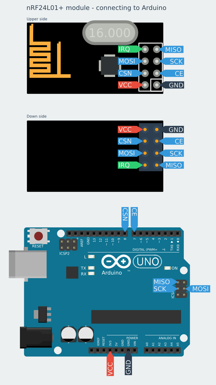
- CONNECTIONS: nRF24L01 Modules See:
http://arduino-info.wikispaces.com/Nrf24L01-2.4GHz-HowTo
1 - GND
2 - VCC 3.3V !!! NOT 5V
3 - CE to Arduino pin 8
4 - CSN to Arduino pin 10
5 - SCK to Arduino pin 13
6 - MOSI to Arduino pin 11
7 - MISO to Arduino pin 12
8 - UNUSED
-
Analog Joystick or two 10K potentiometers:
GND to Arduino GND
VCC to Arduino +5V
X Pot to Arduino A5
Y Pot to Arduino A4
Click Button to pin 4
-V2.00 7/12/14 by Noah King
Based on examples at http://www.airspayce.com/mikem/arduino/RadioHead/index.html
*/
/*-----( Import needed libraries )-----*/
// SEE http://arduino-info.wikispaces.com/Arduino-Libraries !!
// NEED the RadioHead Library installed!
// http://www.airspayce.com/mikem/arduino/RadioHead/RadioHead-1.23.zip
#include <RHReliableDatagram.h>
#include <RH_NRF24.h>
#include <SPI.h>
/*-----( Declare Constants and Pin Numbers )-----*/
#define JoyStick_X_PIN A5 //Pin Numbers
#define JoyStick_Y_PIN A4
#define ClickPIN 4
#define CLIENT_ADDRESS 1 // For Radio Link
#define SERVER_ADDRESS 2
// Create an instance of the radio driver
RH_NRF24 RadioDriver;
// Create an instance of a manager object to manage message delivery and receipt, using the driver declared above
RHReliableDatagram RadioManager(RadioDriver, CLIENT_ADDRESS);// sets the driver to NRF24 and the client adress to 1
/*-----( Declare Variables )-----*/
uint8_t joystick[2]; // 2 element array of unsigned 8-bit type, holding Joystick readings
// Predefine the message buffer here: Don't put this on the stack:
uint8_t buf[RH_NRF24_MAX_MESSAGE_LEN]; // Actually: 28 bytes (32 minus 4 byte header)
void setup() /****** SETUP: RUNS ONCE ******/
{
// begin serial to display on Serial Monitor. Set Serial Monitor to 115200
// See http://arduino-info.wikispaces.com/YourDuino-Serial-Monitor
Serial.begin(115200);
// NOTE: pinMode for Radio pins handled by RadioDriver
if (!RadioManager.init()) // Defaults after init are 2.402 GHz (channel 2), 2Mbps, 0dBm
Serial.println("init failed");
pinMode(ClickPIN, INPUT); //Not really needed: pins default to INPUT
}
void loop() /****** LOOP: RUNS CONSTANTLY ******/
{
//Read the joystick values, scale them to 8-bit type and store them in the joystick[] array.
Serial.println("Reading joystick values ");
// Take the value of Joystick voltages which are 0 to 1023 (10 bit), and convert them to 0 to 255 (8 bit)
joystick[0] = map(analogRead(JoyStick_X_PIN), 0, 1023, 0, 255);
joystick[1] = map(analogRead(JoyStick_Y_PIN), 0, 1023, 0, 255);
//Display the joystick values in the serial monitor.
Serial.print("x:");
Serial.print(joystick[0]);
Serial.print("y:");
Serial.println(joystick[1]);
Serial.println("Sending Joystick data to nrf24_reliable_datagram_server");
//Send a message containing Joystick data to manager_server
if (RadioManager.sendtoWait(joystick, sizeof(joystick), SERVER_ADDRESS))
{
// Now wait for a reply from the server
uint8_t len = sizeof(buf);
uint8_t from;
if (RadioManager.recvfromAckTimeout(buf, &len, 2000, &from))
{
Serial.print("got reply from : 0x");
Serial.print(from, HEX);
Serial.print(": ");
Serial.println((char*)buf);
}
else
{
Serial.println("No reply, is nrf24_reliable_datagram_server running?");
}
}
else
Serial.println("sendtoWait failed");
delay(500); // Wait a bit before next transmission
}
The RECEIVE Software Sketch:
(Copy and paste into a blank Arduino IDE page)/* YourDuinoStarter Example:RECEIVE nRF24L01 Joystick data to control Pan Tilt Servos Over Radio. QUESTIONS? terry@yourduino.com -WHAT IT DOES: -Receives Joystick Analog Values over a nRF24L01 Radio Link, using the Radiohead library. - Sends Joystick position to 2 servos, usually X,Y to pan-tilt arrangement - TODO! Send the Joystick push-down click to turn Laser on and off - SEE the comments after "//" on each line below - CONNECTIONS: nRF24L01 Modules See: http://arduino-info.wikispaces.com/Nrf24L01-2.4GHz-HowTo 1 - GND 2 - VCC 3.3V !!! NOT 5V 3 - CE to Arduino pin 8 4 - CSN to Arduino pin 10 5 - SCK to Arduino pin 13 6 - MOSI to Arduino pin 11 7 - MISO to Arduino pin 12 8 - UNUSED -V2.00 7/12/14 by Noah King Based on examples at http://www.airspayce.com/mikem/arduino/RadioHead/index.html */ /*-----( Import needed libraries )-----*/ // SEE http://arduino-info.wikispaces.com/Arduino-Libraries !! // NEED the SoftwareServo library installed // http://playground.arduino.cc/uploads/ComponentLib/SoftwareServo.zip #include <SoftwareServo.h> // Regular Servo library creates timer conflict! // NEED the RadioHead Library installed! // http://www.airspayce.com/mikem/arduino/RadioHead/RadioHead-1.23.zip #include <RHReliableDatagram.h> #include <RH_NRF24.h> #include <SPI.h> /*-----( Declare Constants and Pin Numbers )-----*/ #define CLIENT_ADDRESS 1 #define SERVER_ADDRESS 2 #define ServoHorizontalPIN 3 //Pin Numbers #define ServoVerticalPIN 5 #define LaserPIN 6 #define ServoMIN_H 0 // Don't go to very end of servo travel #define ServoMAX_H 160 // which may not be all the way from 0 to 180. #define ServoMIN_V 0 // Don't go to very end of servo travel #define ServoMAX_V 140 // which may not be all the way from 0 to 180. /*-----( Declare objects )-----*/ SoftwareServo HorizontalServo; SoftwareServo VerticalServo; // create servo objects to control servos // Create an instance of the radio driver RH_NRF24 RadioDriver; // Create an instance of a manager object to manage message delivery and receipt, using the driver declared above RHReliableDatagram RadioManager(RadioDriver, SERVER_ADDRESS); /*-----( Declare Variables )-----*/ int HorizontalJoystickReceived; // Variable to store received Joystick values int HorizontalServoPosition; // variable to store the servo position int VerticalJoystickReceived; // Variable to store received Joystick values int VerticalServoPosition; // variable to store the servo position uint8_t ReturnMessage[] = "JoyStick Data Received"; // 28 MAX // Predefine the message buffer here: Don't put this on the stack: uint8_t buf[RH_NRF24_MAX_MESSAGE_LEN]; //--------------------------------( SETUP Runs ONCE )----------------------------------------------------- void setup() { pinMode(LaserPIN, OUTPUT); digitalWrite(LaserPIN, HIGH); // turn on Laser /*-----( Set up servos )-----*/ HorizontalServo.attach(ServoHorizontalPIN); // attaches the servo to the servo object VerticalServo.attach(ServoVerticalPIN); // attaches the servo to the servo object // begin serial to display on Serial Monitor. Set Serial Monitor to 115200 // See http://arduino-info.wikispaces.com/YourDuino-Serial-Monitor Serial.begin(115200); if (!RadioManager.init()) // Initialize radio. If NOT "1" received, it failed. Serial.println("init failed"); // Defaults after init are 2.402 GHz (channel 2), 2Mbps, 0dBm } // END Setup //--------------------------------( LOOP runs continuously )----------------------------------------------------- void loop() { if (RadioManager.available()) { // Wait for a message addressed to us from the client uint8_t len = sizeof(buf); uint8_t from; if (RadioManager.recvfromAck(buf, &len, &from)) //Serial Print the values of joystick { Serial.print("got request from : 0x"); Serial.print(from, HEX); Serial.print(": X = "); Serial.println(buf[0]); Serial.print(" Y = "); Serial.println(buf[1]); // Send a reply back to the originator client, check for error if (!RadioManager.sendtoWait(ReturnMessage, sizeof(ReturnMessage), from)) Serial.println("sendtoWait failed"); }// end 'IF Received data Available }// end 'IF RadioManager Available { SoftwareServo::refresh();//refreshes servo to keep them updating HorizontalJoystickReceived = buf[1]; // Get the values received VerticalJoystickReceived = buf[0]; // scale it to use it with the servo (value between MIN and MAX) HorizontalServoPosition = map(HorizontalJoystickReceived, 0, 255, ServoMIN_H , ServoMAX_H); VerticalServoPosition = map(VerticalJoystickReceived, 0, 255, ServoMIN_V , ServoMAX_V); Serial.print("HorizontalServoPosition : "); Serial.print(HorizontalServoPosition); Serial.print(" VerticalServoPosition : "); Serial.println(VerticalServoPosition); // tell servos to go to position HorizontalServo.write(HorizontalServoPosition); VerticalServo.write(VerticalServoPosition); delay(25); // wait for the servo to reach the position } }// END Main LOOP
دانلود آموزش فارسی راه اندازی ماژول وایرلس NRF24L01


 by
by
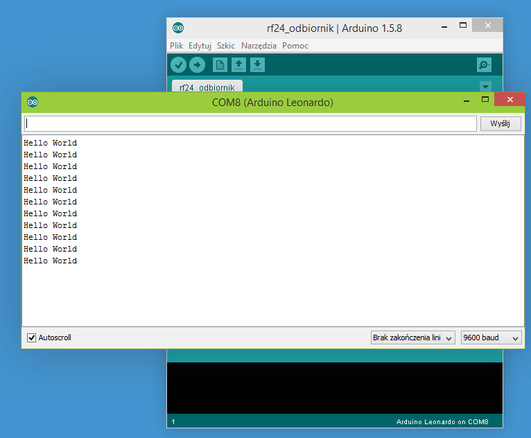
I was having problem with NRF24 for almost 2 weeks now (Arduino and Raspberry Pi). This is due to many misleading information out there that doesn’t work or confusing or too much information that not required for basic “Hello World” program.
After spending lots of time trying sample scripts that doesn’t work, I was almost gave up. Finally, found your website with super simple script and worked like charm on first attempt.
Your graphical guide (clean and clear) helps a lot in getting the pins connected without mistakes.
Step by step explanation on script lines helps to understand it’s function more clearer. In fact it’s a great “Hello World” tutorial that everyone can get started without issue.
Now only I know that only few lines of codes needed and it’s enough to test NRF24 “Hello World” program.
Keep up your good work. Thank you.
Hello i tried your sketch and it works thank you. But the problem I’m having is that the delay receiving it on the serial monitor is very slow it’s like instead of 1 second i get like a 5 second delay. i try to take out the delay that seems to go faster but then i get instead of a hello world once i get it like 3 times at once. can someone please help me out? thank you.
If there are radio interferences nrf makes few tries to send – maybe this is the case? Something is interfering – can You make test in another environment?
Second guess is that after some work we find that Mirf library (https://github.com/stanleyseow/arduino-nrf24l01 ) is much better in terms of stability. We will write some examples in future, but right now You can take a look at codehttps://github.com/nettigo/TinnySensorModule This sketch is for ATtiny84, but inside is folder with code for UNO to receive data.
Hi, I tried your code and it works for one or two lines but then it starts outputting gobbeltygook forever.
I’m not sure what’s going on here. At first I had the pins you point out as 7 and 8 as 9 and 10 so I changed them to 7 and 8 but it does the same thing.
new to all this – getting ARduino IDE 1.6.3 compile error shown below. I have a feeling something is pointing to the wrong area so it is not picking up all the libraries but cannot figure it out. I’ve tried changing the in the include statements to “xxx” but no change. Would greatly appreciate any help you can offer.
Arduino: 1.6.3 (Windows 7), Board: “Pro Trinket 3V/12MHz (FTDI)”
These errors are related to changes in newer IDE and compiler. I think if You fallback to 1.5.x it will work.
We plan to rewrite examples to Mirf library using newer IDE, but I can not give any estimate when it can happen.
Thank you for the info. I’ll keep plugging away at it.
Since NRF24l01 sends max of 32 bytes at a time, how do you go about sending a set of information that has 150 bytes?
What if instead of test you are sending numbers?
I am trying to send a bunch of data from some sensors.
Thanks
I was having trouble with the Arduino Micro and the NRF24l01. I found the solution on this web page
http://minspan.blogspot.com/2014/06/nrf24l01-rf24-radio-on-arduino-micro.html
Basically, the ICSP are not hooked up or hooked up wrong. You will have to use pin 11 for MISO, pin 9 for SCK, pin 10 for MOSI. The mentioned website explains it further.
Hello,
Very nice and simple Hello world example. It is pretty useful as a beginner.
No I have a question for you. Have tried to set a network of more than one nrf24l01?
i am working on the project where I am making a network4 nrf24l01 transceivers, such that one can broadcast the text message from one transceiver at the base station to all the other transceivers connected to it. After receiving the message, the transceiver should reply back to the base station in same manner.
I need your some guidance in the coding. What should be the code at base station and what could be the code at other node?
Please help..It’s urgent!!!
Thank you
can u post the schemetics for the both the transmitter and the reciever i am confused ….
should i use 2 arduino and 2 nrfl01 for communications ????? plz help some
Hi,
Thanks a lot for this tutorial. It’s great and probably the best in whole web.
I’ve run this exaple on my Arduino Due boards. I’ve just needed to write #define RF24_DUE in the code to make it works. Everything is correct and i am sending and receiving messegas on my boards.
Now I have to use the nrf24lo1 transmission with my usb host shield which uses SPI too. Does somebody knows how to initialize SPI in code for two devices – usb host shield and nrf24l01 in this case, (maybe some hardware changes are needed?)
I found the information in datasheet that shield uses pin 10 as a CS PIN, so i’ve changed it for nrf to pin 4. When i did that and stopped using port 10 for nrf24l01 my program doesn’t work anymore. I cannot even write anything on terminal using Serial.println() function.
If i use pin 10 for nrf CS again Serial port works, but nrf transmission doesn’t work.
Maybe somebody could help me.
I have an UNO and on the other hand a MEGA. The UNO works fine as a transmitter when I connect it with an external power supply where the MEGA is connected as the receiver to the computer. But when i do the vice versa of it (MEGA as transmitter and UNO as receiver) and i connect MEGA to the external power supply, no packets are received and no change is captured. Can you suggest me a solution to my problem?
These instructions worked great!
I have the ADDICORE nRF24L01+ kit and had this running within an hour. The kit comes with Male-Female connectors so it was easier to connect from the RF board to the Arduino on the digital input pins (11, 12, 13) instead of the ICSP pins.
How do I send numeric data? I need to send a byte, not text.
Thanks in advance to whoever can post some simple Arduino code to answer this question.
I figured out one way to send a number instead of a string:
Thanks a lot!
Hello
I have error in compiling here:
radio.openWritingPipe(rxAddr);
error message is here:
Arduino: 1.6.6 Hourly Build 2015/08/07 05:34 (Windows 8.1), Board: “Arduino Uno”
can help please
thanks
دانلود آموزش فارسی  راه اندازی ماژول وایرلس NRF24L01
+کدهای گیرنده و فرستنده+کتابخانه+پاورپوینت توضیحات و شماتیک
در قالب یک پروژه کاملا عملی